Oil Filled Transformer: Complete Technical Guide & Selection Manual (2026)
An oil filled transformer uses insulating liquid to cool its core and windings while providing dielectric protection, making it the dominant technology for outdoor substations, utility grids, and large-scale industrial applications worldwide. Choosing the wrong sub-type or fluid for your environment can shorten service life by years, increase maintenance costs, or create safety risks that could have been avoided with the right specification.
A procurement team for a 50 MW solar farm in North Africa learned this during their first project phase. They specified standard conservator-type transformers with mineral oil, a common and cost-effective choice. But the extreme diurnal temperature swings, ranging from 15°C at night to 48°C during the day, caused rapid oil oxidation. Within three years, acidity levels climbed past the IEEE C57.106 threshold of 0.3 mg KOH/g, and oil color darkened beyond acceptable limits. The project faced unplanned oil replacement costs of $28,000 and transformer downtime during peak generation season. Phase two switched to natural ester fluid with superior oxidation stability, and those units have operated for five years without degradation. The total cost difference was 18% upfront. The operational difference was years of reliable service.
This guide explains what an oil filled transformer is, how the technology works, the differences between sub-types and fluids, and how to select the right design for your application.
Key Takeaways
- Oil filled transformers use liquid insulation for superior cooling and dielectric strength, dominating outdoor and high-capacity applications.
- Three sub-types exist: conservator-type (most common, with expansion tank), hermetically sealed (welded tank, no air contact), and sealed-tank with gas cushion.
- Fluid selection matters as much as hardware: mineral oil is standard, natural ester offers 300°C+ flash point and biodegradability, silicone provides extreme fire safety at the highest cost.
- Oil filled transformers are typically 1-2% more efficient than equivalent dry type units and serve 25-40 years with proper maintenance.
- Selection requires matching sub-type, fluid, cooling method, and efficiency class to the specific application and environment.
What is an oil-filled transformer?
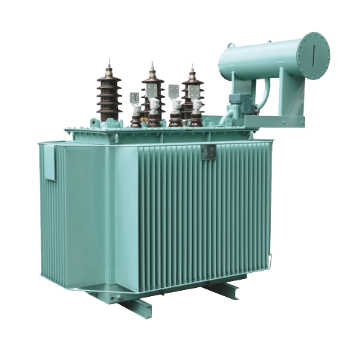
An oil-filled transformer is an electrical device that transfers energy between circuits through electromagnetic induction, using a liquid dielectric medium to insulate windings and dissipate heat. The insulating fluid fills the transformer tank, surrounding the core and coil assembly, and performs two functions that air or solid insulation cannot match at equivalent ratings: it provides high dielectric strength (typically 70 kV or higher for new mineral oil) and carries heat away from windings through natural or forced circulation.
Basic Construction
The core components of an oil filled transformer include:
- Core: Laminated grain-oriented silicon steel that carries magnetic flux
- Windings: Copper or aluminum conductors forming primary and secondary coils
- Tank: Steel enclosure that contains the core, windings, and insulating fluid
- Bushings: Insulated conductors that pass through the tank wall to external connections
- Cooling system: Radiators, fans, or heat exchangers that dissipate thermal energy
- Conservator or expansion system: Manages oil volume changes with temperature
Why Oil?
Liquid insulation offers advantages that solid or air insulation cannot replicate at medium and high capacities. Oil has approximately 2.5 times the heat capacity of air by volume, which means it can absorb and transport more thermal energy per unit of circulation. This allows oil filled transformers to operate at higher continuous loads and greater kVA ratings than dry type alternatives of similar physical size. The dielectric strength of new mineral oil, approximately 70 kV across a standard test gap, exceeds that of air by a factor of roughly five, enabling more compact winding designs at higher voltages.
Need a refresher on transformer fundamentals? See our distribution transformer guide for the basics of voltage transformation before selecting a specific type.
How Oil Filled Transformers Work
Electromagnetic Induction Principle
Like all transformers, an oil filled unit operates on electromagnetic induction. Alternating current in the primary winding creates a changing magnetic field in the core. This field induces a voltage in the secondary winding proportional to the turns ratio between the two coils. The oil does not participate in the electromagnetic process itself, but it enables the physical design that makes high-power transformation practical.
Oil Circulation and Heat Transfer
Heat generation in a transformer comes from two sources: core losses (hysteresis and eddy currents in the steel) and load losses (resistive heating in the windings). At full load, a 1,000 kVA transformer can generate 8-12 kW of heat that must be dissipated to prevent insulation damage.
Oil circulation follows temperature gradients. Hot oil rises from the top of the windings, flows through cooling channels or radiators where it releases heat to ambient air, and returns to the bottom of the tank to repeat the cycle. This natural circulation is called ONAN (Oil Natural, Air Natural). For higher capacities or hotter environments, forced circulation modes add fans or pumps:
| Cooling Mode | Code | Description | Typical Application |
|---|---|---|---|
| Oil Natural, Air Natural | ONAN | Natural convection, no moving parts | Standard distribution up to ~5 MVA |
| Oil Natural, Air Forced | ONAF | Natural oil flow, forced air over radiators | Medium power, ~5-20 MVA |
| Oil Forced, Air Forced | OFAF | Forced oil and air circulation | Large power transformers |
| Oil Forced, Air Directed | ODAF | Directed oil flow through windings | Extra-high-voltage units |
Temperature Rise and Insulation Aging
IEC 60076-2 specifies temperature rise limits for oil filled transformers: 60°C average winding rise and 78°C hot-spot rise above ambient, measured by resistance. The hot-spot temperature, typically 10-15°C above the average winding temperature, is the critical factor in insulation aging. For every 6°C increase in hot-spot temperature above 98°C, the rate of insulation paper aging doubles. Proper cooling design and oil quality maintenance are therefore essential for achieving the rated 25-40 year service life.
Types of Oil Filled Transformers
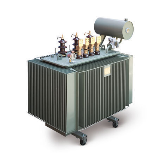
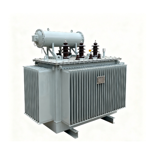
Conservator-Type Transformers
The conservator-type design is the most common configuration for oil filled transformers. A separate expansion tank (conservator) mounted above the main tank accommodates oil volume changes caused by temperature fluctuations. A pipe connects the conservator to the main tank, and a breather filled with silica gel removes moisture from air entering and leaving the expansion space.
This design is cost-effective, well-understood, and easy to maintain. Oil sampling, testing, and filtration are straightforward because the conservator provides access to the oil volume. The trade-off is that the oil remains in contact with air (after passing through the breather), which introduces oxygen and moisture that gradually degrade the fluid over time.
Hermetically Sealed Transformers
Hermetically sealed transformers use a fully welded tank with no breathing system. The oil is sealed inside at the factory, and a nitrogen cushion or flexible membrane accommodates thermal expansion without allowing air contact. Because the oil never meets atmospheric oxygen, oxidation rates drop dramatically. Oil life can extend two to three times compared to conservator-type designs.
An industrial plant on the coast of Southeast Asia specified standard conservator-type units for their humid, salt-laden environment. The silica gel breather saturated within weeks during monsoon season, allowing moist air to enter the conservator. Oil dielectric strength fell from 70 kV to 45 kV in 18 months, and dissolved gas analysis revealed elevated moisture content. The maintenance team spent $4,000 annually on silica gel replacement and oil drying. When the facility expanded, they selected hermetically sealed transformers. The welded tanks eliminated the breathing system entirely, and dielectric strength has remained stable for four years without intervention.
Hermetically sealed designs are ideal for humid, coastal, dusty, or remote locations where regular maintenance access is limited. The trade-off is that oil cannot be sampled or filtered without breaking the seal, so initial oil quality must be high, and the design must account for the full service life of the fluid.
Sealed-Tank with Gas Cushion
A middle-ground design uses a sealed tank with a pressurized gas cushion (typically nitrogen) above the oil surface. This reduces air contact compared to a conservator but does not eliminate it entirely. The gas cushion compresses and expands with temperature changes, maintaining positive pressure inside the tank that inhibits moisture ingress. This design is less common than the other two but offers a balance of extended oil life and serviceability.
Selection Guidance
| Factor | Conservator-Type | Hermetically Sealed | Sealed-Tank with Gas Cushion |
|---|---|---|---|
| Initial cost | Lowest | Moderate | Moderate |
| Maintenance access | Easy (sampling, filtration) | Limited (sealed) | Moderate |
| Oil life | 15-25 years | 30-40+ years | 20-30 years |
| Best environment | Controlled, accessible | Humid, coastal, remote | Moderate conditions |
| Moisture risk | Moderate (breather dependent) | Very low | Low |
| Serviceability | High | Low | Moderate |
For a deep dive into hermetically sealed design, see our dedicated hermetically sealed transformer guide.
Transformer Oil Types and Fluids
The insulating fluid in an oil filled transformer is not a commodity afterthought. It is an active component that determines fire safety, environmental impact, oxidation stability, and in some cases, thermal performance.
Mineral Oil
Mineral oil, refined from petroleum, is the standard insulating fluid for approximately 85% of installed oil filled transformers. It offers excellent dielectric properties, good heat transfer characteristics, and the lowest initial cost. Standard mineral oil has a flash point of approximately 140°C and a fire point around 160°C.
The primary limitation of mineral oil is flammability. In indoor installations or environments near buildings, mineral oil creates fire safety concerns that may require containment pits, fire suppression systems, or vault construction. It is also not readily biodegradable, creating environmental risk in the event of a spill.
Natural Ester
Natural ester fluids, derived from seed oils such as soybean or rapeseed, have emerged as the leading alternative to mineral oil. Their flash point exceeds 300°C, more than double that of mineral oil, which significantly reduces fire risk. Natural esters are fully biodegradable, meeting OECD 301 standards for environmental safety.
Natural ester also absorbs moisture from insulation paper, which can slow the aging of cellulose-based insulation and extend transformer life. The trade-offs are a 15-30% price premium over mineral oil and slightly higher viscosity at low temperatures, which may affect cold-start performance in extreme climates.
Synthetic Ester
Synthetic ester fluids offer the highest fire safety classification (K3 per IEC 61039) with flash points above 300°C and exceptional oxidation stability. They perform well across a wide temperature range and are biodegradable. Synthetic esters are typically used in applications where fire risk must be minimized and natural ester viscosity characteristics are insufficient, such as in cold climates or high-altitude installations. The cost is higher than natural ester.
Silicone
Silicone-based insulating fluids provide extreme fire safety with flash points above 300°C and essentially no propagation of flame. They are chemically stable and non-toxic. The primary drawback is cost: silicone fluid can cost 4-5 times more than mineral oil. Silicone is typically reserved for indoor installations, high-rise buildings, or other applications where fire codes prohibit less flammable alternatives and dry type units are not practical due to capacity requirements.
Fluid Comparison Table
| Property | Mineral Oil | Natural Ester | Synthetic Ester | Silicone |
|---|---|---|---|---|
| Flash point | ~140°C | >300°C | >300°C | >300°C |
| Fire point | ~160°C | >350°C | >350°C | >350°C |
| Biodegradable | No | Yes | Yes | No |
| Cost vs mineral | 1.0x | 1.15-1.30x | 1.40-1.60x | 4.0-5.0x |
| Oxidation stability | Good | Good | Excellent | Excellent |
| Moisture absorption | Low | High (beneficial) | Moderate | Very low |
| Typical application | Standard outdoor | Renewable, indoor, sensitive | Cold climate, critical | High-rise, indoor |
For a complete fluid comparison with selection guidance, see our transformer oil types guide.
Oil Filled Transformer vs Dry Type Transformer
Buyers often face a choice between oil filled and dry type transformers. The right decision depends on application, environment, capacity, and lifecycle cost perspective.
Efficiency Comparison
Oil filled transformers are typically 1-2% more efficient than equivalent dry type units at full load. This difference comes from superior cooling: oil removes heat more effectively than air, allowing lower operating temperatures for the same output. Over 25 years of service, a 1% efficiency improvement on a 2,500 kVA transformer operating at 75% load can save 150,000-200,000 kWh, depending on local electricity rates.
Fire Safety and Installation Codes
Dry type transformers use no flammable liquid, making them the default choice for indoor installations in hospitals, data centers, schools, and commercial buildings where fire codes restrict liquid-filled equipment. Oil filled transformers can be used indoors only in vaults or dedicated rooms with fire containment, ventilation, and suppression systems per NFPA 70 (NEC Article 450) or local equivalents.
For outdoor applications, the fire safety advantage of dry type diminishes. Oil filled units placed on outdoor pads or in substations face no indoor fire code restrictions, and natural ester or synthetic ester fluids can further reduce fire risk.
Installation Requirements
Dry type transformers require no containment pits or oil spill prevention systems. Oil filled units need concrete pads with oil containment (typically 110% of total oil volume), fire walls if placed near buildings, and adequate clearance for radiator maintenance and oil handling. These civil works add to upfront project cost but are standard for outdoor infrastructure.
Maintenance Burden
Dry type transformers require minimal maintenance: periodic cleaning, torque checks, and infrared thermography. Oil filled transformers require annual or biennial oil testing (dissolved gas analysis, dielectric strength, moisture content, acidity), breather maintenance for conservator types, and eventual oil replacement or reclamation. The maintenance burden is higher but predictable, and modern condition monitoring can optimize test intervals.
Total Cost of Ownership
| Cost Factor | Oil Filled | Dry Type |
|---|---|---|
| Upfront unit cost | Lower per kVA | Higher per kVA |
| Civil works | Higher (containment, pad) | Lower |
| Installation | Moderate | Lower |
| Operating losses | Lower (1-2% more efficient) | Higher |
| Maintenance | Higher (oil testing, filtration) | Lower |
| Service life | 25-40 years | 20-35 years |
| End-of-life disposal | Oil reclamation required | Standard recycling |
For outdoor utility, industrial, and renewable energy applications where capacity exceeds approximately 2,500 kVA, oil filled transformers typically deliver lower total cost of ownership over their service life. For indoor commercial and safety-critical applications below 2,500 kVA, dry type is usually the better choice.
For a complete comparison with TCO analysis, see our dry type vs oil filled transformer guide. For indoor applications, see our dry type transformer guide.
Oil Filled Transformer Specifications and Standards
Capacity and Voltage Ranges
Oil filled transformers cover the widest range of any transformer technology:
- Distribution transformers: 50 kVA to 5,000 kVA, typically 11 kV or 33 kV primary
- Power transformers: 5 MVA to 50 MVA+, up to 245 kV in utility applications
- Extra-high-voltage transformers: Above 245 kV, used in transmission grids up to 765 kV
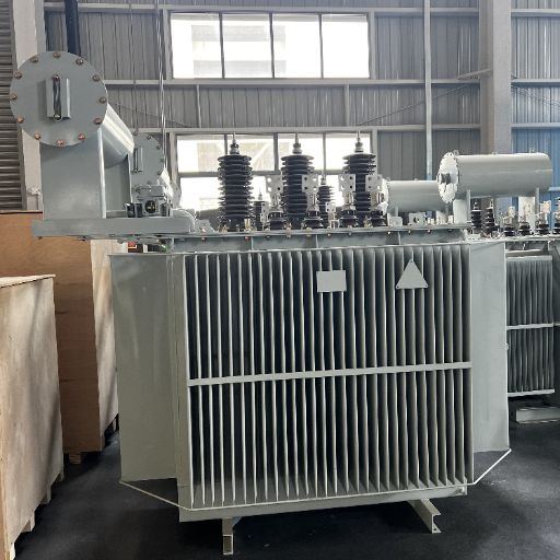
Shandong Electric Co., Ltd. manufactures oil immersed transformers from 50 kVA to 50 MVA, covering distribution through medium-power applications.
International Standards
| Standard | Scope | Region |
|---|---|---|
| IEC 60076-1 | General requirements for power transformers | Global |
| IEC 60076-2 | Temperature rise | Global |
| IEC 60076-3 | Insulation levels, dielectric tests | Global |
| IEC 60076-5 | Ability to withstand short circuit | Global |
| IEEE C57.12.00 | General requirements | North America |
| IEEE C57.12.90 | Test code | North America |
| ANSI C57.12.10 | Dry-type and liquid-immersed | North America |
Efficiency Standards
Efficiency requirements vary by market. The U.S. Department of Energy (DOE) sets minimum efficiency levels for liquid-immersed distribution transformers per 10 CFR Part 431. The European Union EcoDesign Directive (Commission Regulation 548/2014) mandates maximum loss values for transformers placed on the EU market. China follows GB standards that align closely with IEC requirements. Buyers should verify that efficiency claims are supported by third-party test reports, not just manufacturer declarations.
Applications of Oil Filled Transformers
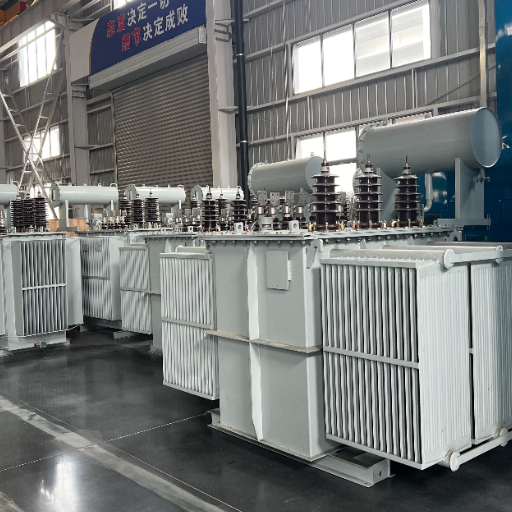
Utility Substations
Oil filled transformers are the backbone of electrical transmission and distribution networks. Step-down transformers in substations reduce transmission voltages (66 kV, 110 kV, 220 kV) to distribution levels (11 kV, 33 kV). Their high efficiency and overload capacity make them essential for grid stability. Conservator-type designs dominate utility applications due to ease of maintenance and established service infrastructure.
For substation-specific design guidance, see our oil filled transformer for substation guide.
Solar Farms
Solar photovoltaic plants require step-up transformers to increase inverter output voltage (typically 400-800 V AC) to medium voltage (11-33 kV) for collection and transmission. Oil filled transformers dominate this application due to their outdoor placement, capacity requirements (500-5,000 kVA per unit), and cost efficiency. Hermetically sealed designs are increasingly popular in desert and coastal solar projects where maintenance access is limited and environmental conditions are harsh.
Wind Farms
Wind turbines generate variable-frequency power that is converted to grid-frequency AC before entering a step-up transformer. Oil filled units rated 1,500-3,500 kVA raise voltage from 690 V to 33 kV for collection. The nacelle or tower-base transformer must withstand vibration, temperature cycling, and remote location challenges.
Industrial Plants
Manufacturing facilities, refineries, and mining operations use oil filled transformers for main substations and large motor loads. Capacities range from 1,000 kVA for small plants to 20 MVA+ for heavy industrial complexes. The overload capability of oil filled designs is valuable in industrial settings where motor starting currents and intermittent peak loads exceed continuous ratings.
Mining and Remote Sites
Hermetically sealed oil filled transformers are preferred for mining and remote installations due to their sealed construction, reduced maintenance requirements, and resilience in dusty or corrosive environments. These locations often lack skilled maintenance staff, making the long oil life of sealed designs a practical necessity.
Rural Distribution
Pole-mounted and pad-mounted oil filled transformers serve rural and suburban distribution networks. Ratings typically range from 25 kVA to 500 kVA, stepping down 11 kV or 33 kV to 400/230 V for residential and small commercial consumers. Pad-mounted units with dead-front bushings and tamper-resistant enclosures are standard for underground residential distribution in North America.
For pad-mounted distribution transformers, see our pad mounted transformer guide
Installation and Maintenance Overview
Foundation and Containment
Oil filled transformers require a level concrete pad designed to support the unit weight plus oil volume. A containment system must capture 110% of the total oil volume in case of rupture or leakage. For large units, foundation design must account for seismic loads per local building codes and transformer manufacturer specifications. Cable trenches route primary and secondary conductors to the transformer location while maintaining bending radius requirements for insulated cables.
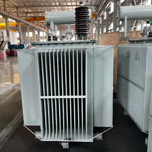
Cooling Clearance
Radiators and cooling banks require unobstructed air flow. Minimum clearances vary by manufacturer but typically require 1-1.5 meters of open space on radiator faces and 0.6-1 meter on non-radiator sides. ONAF and OFAF units need additional clearance for fan maintenance access. Vegetation management around outdoor installations prevents airflow obstruction and fire risk.
Oil Testing Schedule
A predictive maintenance program for oil filled transformers should include:
- Annual: Dissolved gas analysis (DGA), dielectric breakdown voltage, moisture content (ppm), visual inspection
- Biennial: Acidity, interfacial tension, color, power factor
- As needed: Furan analysis (insulation paper aging), particle count, PCB screening (for older units)
DGA is the most powerful predictive tool. Key gas thresholds per IEEE C57.104 include:
| Gas | Threshold (ppm) | Interpretation |
|---|---|---|
| Hydrogen (H2) | 100 | Corona, partial discharge |
| Methane (CH4) | 120 | Low-energy thermal fault |
| Ethylene (C2H4) | 50 | High-energy thermal fault |
| Acetylene (C2H2) | 1 | Arcing (critical) |
| Carbon monoxide (CO) | 350 | Paper insulation overheating |
| Carbon dioxide (CO2) | 2,500 | Normal aging or overheating |
For detailed testing procedures and maintenance schedules, see our transformer oil testing and maintenance guide.
Filtration vs Replacement
When oil tests reveal degradation, two options exist. Filtration and reclamation remove moisture, dissolved gases, and particulate contamination while restoring dielectric strength. This is cost-effective when acidity remains below 0.3 mg KOH/g and no severe gas generation has occurred. Oil replacement is necessary when acidity exceeds limits, sludge has formed, or reclamation cannot restore properties. Replacement typically costs 3-5 times more than filtration but may be the only viable option for severely degraded oil.
For outdoor installation details including foundation design and grounding, see our outdoor transformer installation guide.
How to Choose the Right Oil Filled Transformer
Selection is a multi-step process that matches technical requirements to environmental constraints and lifecycle cost objectives.
Step 1:Define Application and Environment
Start with the operating context. Is the transformer for a utility substation, solar farm, industrial plant, or rural distribution? Will it be installed outdoors in a temperate climate, a desert, a coastal area, or indoors in a vault? The environment determines sub-type, fluid, cooling method, and enclosure requirements.
Step 2:Select Sub-Type
Choose conservator-type for standard outdoor applications with accessible maintenance. Choose hermetically sealed for humid, coastal, dusty, or remote locations where minimizing maintenance is a priority. Choose sealed-tank with gas cushion only when a specific project requirement dictates this intermediate design.
Step 3:Choose Fluid Type
Mineral oil is the default for cost-sensitive outdoor utility and industrial projects where fire codes permit. Natural ester is the right choice for renewable energy projects, installations near buildings or water sources, and any application where biodegradability and fire safety justify a 15-30% premium. Synthetic ester serves cold climates and critical applications. Silicone is reserved for high-rise or indoor installations where maximum fire safety is required and budget allows.
Step 4:Determine Capacity and Voltage Class
Calculate required kVA based on connected load, diversity factors, and future growth. Standard distribution ratings follow preferred numbers: 100, 250, 500, 1,000, 1,500, 2,000, 2,500 kVA. Specify primary and secondary voltages, vector group (e.g., Dyn11), impedance, and tap changer requirements.
For 11 kV specification details, see our 11kV oil-filled transformer guide.
Step 5:Specify Cooling and Efficiency Class
ONAN cooling is sufficient for most distribution transformers up to approximately 5 MVA. ONAF extends capacity by 20-30% without increasing unit size. Specify efficiency class per local regulations (DOE Tier, EU EcoDesign) and evaluate total cost of ownership across 20-30 years, not just purchase price.
A utility substation upgrade team in Eastern Europe focused exclusively on purchase price when replacing 30-year-old units. They specified the minimum efficiency class allowed by local regulation. An engineering review commissioned after award revealed that selecting one efficiency tier higher would have reduced no-load losses by 15%. Over 25 years, the incremental energy savings exceeded the purchase price premium by a factor of three. The procurement team had optimized for capital expenditure while the real cost driver was operating expenditure.
Step 6:Evaluate Manufacturer Capability
Verify that the manufacturer has experience with the specific sub-type, fluid, and voltage class you need. Request type-test certificates from accredited laboratories (KEMA, CESI, UL) for the design family. Confirm in-house testing capability for routine tests on every unit. For export orders, verify that the manufacturer provides complete documentation including oil certificates, MSDS, and compliance certificates.
For manufacturer evaluation guidance, see our oil transformer manufacturer guide.
Frequently Asked Questions
How long do oil filled transformers last?
With proper maintenance, oil filled transformers typically serve 25-40 years. Conservator-type units with mineral oil may require oil replacement or reclamation at 15-25 years. Hermetically sealed units can exceed 40 years because the sealed environment prevents oil oxidation. Insulation paper life, not oil quality, often becomes the limiting factor after 30+ years.
Can oil filled transformers be used indoors?
Yes, but indoor installation requires compliance with fire safety codes. NFPA 70 (NEC Article 450) and IEC 61936-1 specify vault construction, fire containment, ventilation, and oil spill prevention for indoor liquid-filled transformers. Natural ester or synthetic ester fluids reduce fire risk and may simplify code compliance. For most indoor applications below 2,500 kVA, dry type transformers are the more practical choice.
What is the difference between conservator and hermetically sealed transformers?
A conservator-type transformer has a separate expansion tank that allows oil to breathe through a silica gel breather, exposing the oil to atmospheric oxygen and moisture. A hermetically sealed transformer uses a welded tank with no breathing system, typically with a nitrogen cushion or flexible membrane to accommodate expansion. Hermetically sealed designs eliminate air contact, extending oil life and reducing maintenance but limiting oil serviceability.
Are oil filled transformers safe?
Oil filled transformers are safe when properly installed, maintained, and protected. Modern designs include pressure relief devices, Buchholz relays (for conservator types), temperature monitoring, and fire protection systems. Natural ester and synthetic ester fluids significantly reduce fire risk compared to mineral oil. The primary safety risk is uncontrolled oil ignition during internal faults, which proper protection systems and installation practices mitigate.
How often should transformer oil be tested?
Dissolved gas analysis and dielectric breakdown voltage should be tested annually for critical units and every 1-2 years for standard distribution transformers. Acidity, interfacial tension, and moisture content should be checked biennially. Transformers in harsh environments (high temperature, humidity, or pollution) may need more frequent testing.
What is the most efficient cooling method?
ODAF (Oil Directed, Air Forced) provides the highest heat removal capacity and allows the greatest power density, but it requires pumps and fans with associated maintenance and energy consumption. For most distribution and medium-power applications, ONAN or ONAF provides the best balance of efficiency, reliability, and cost. The optimal cooling method depends on load profile, ambient conditions, and space constraints.
Can transformer oil be replaced with ester fluid?
Yes, retrofilling mineral oil with natural ester is technically feasible and has been performed on thousands of units. The process requires complete draining, flushing, and refilling with ester fluid, plus verification of compatibility with gaskets and seals. Retrofill is most cost-effective when mineral oil requires replacement anyway due to degradation. New units should be specified with ester from the factory to avoid conversion costs.
What causes transformer oil to degrade?
The primary degradation mechanisms are oxidation (reaction with oxygen), thermal aging (high temperature acceleration), and moisture contamination. Oxidation produces acids, sludge, and increased viscosity. Thermal stress breaks down hydrocarbon molecules and generates dissolved gases. Moisture reduces dielectric strength and accelerates paper insulation aging. Regular testing and filtration address all three mechanisms before they cause failure.
Conclusion
An oil filled transformer is not a generic commodity. It is a system in which the tank design, insulating fluid, cooling method, and voltage class must all match the application and environment. The conservator-type design that serves a temperate utility substation for 30 years may fail prematurely in a coastal solar farm. The mineral oil that minimizes upfront cost may generate hidden expenses through oxidation, fire protection requirements, or environmental liability.
The right oil filled transformer delivers reliable service for decades at low operating cost. The wrong one delivers maintenance burdens, efficiency losses, and premature replacement.
Start by defining your environment and application. Match the sub-type to maintenance access and atmospheric conditions. Select the fluid based on fire safety, environmental, and cost requirements. Size the unit for present load plus future growth. And evaluate manufacturers on testing capability, certification, and export experience before comparing prices.
Ready to specify an oil filled transformer for your project? Send us your voltage, kVA, application, and installation environment. Our engineering team will recommend the optimal sub-type, fluid, and cooling configuration, and provide a detailed quotation with lead time and certification coverage.