Outdoor Transformer Installation: Complete Guide & Best Practices
Installing an outdoor transformer requires coordinated civil, electrical, and environmental preparation before the unit ever reaches the site. A single oversight in foundation design, oil containment, or grounding can create safety risks, regulatory violations, or project delays that cost far more than the transformer itself.
In 2022, an EPC contractor in West Africa installed a 1,500 kVA oil-immersed transformer for a manufacturing plant expansion. The concrete pad was poured to standard dimensions without a geotechnical survey. The local soil, a compressible laterite with poor bearing capacity, settled unevenly under the 8-ton unit. Within six months, the pad had tilted 40 mm. Bushing stress caused a slow oil leak at the HV terminal. The leak went unnoticed for weeks until a routine inspection revealed oil pooling around the pad base. Remediation required a full pad replacement with deep pile foundations, transformer repositioning, and bushing replacement. The initial savings of skipping a soil test cost the project $38,000 and three weeks of production downtime.
This guide covers the complete outdoor transformer installation workflow from site survey through commissioning. You will learn foundation design, oil containment requirements, grounding practices, fire safety clearances, and the pre-energization tests that prevent failures.
Key Takeaways
- Outdoor transformer installation requires civil preparation (foundation, containment, drainage), electrical work (connections, grounding, protection), and environmental compliance before the unit arrives.
- Concrete pads must support the transformer dead weight plus a 25% dynamic load factor, with levelness within ±3 mm per meter.
- Oil containment systems must hold 110% of total oil volume per IEC 61936-1, with spill detection and drainage separation.
- Grounding electrode design must achieve ≤5 ohms resistance for distribution transformers and integrate with the site grounding grid per IEEE 80.
- Pre-energization inspection and commissioning tests detect transport damage, moisture ingress, and connection errors before load is applied.
For detailed information on oil-immersed transformer selection (including oil selection), please refer to our oil-immersed transformer guide.
Pre-Installation Site Survey and Planning
Successful outdoor transformer installation begins weeks before delivery. The site survey identifies constraints that affect pad design, access routing, and regulatory compliance.
Site Selection Criteria
Select a location that provides:
- Adequate space for the transformer footprint plus maintenance clearances on all sides
- Level ground with natural or engineered drainage away from the unit
- Access for delivery vehicles, cranes, and future maintenance equipment
- Proximity to primary and secondary cable routes without excessive run lengths
- Separation from buildings, property lines, and ignition sources per fire codes
Environmental Assessment
Document ambient conditions that affect transformer performance and installation planning:
- Maximum and minimum temperatures (affects cooling design and oil viscosity)
- Wind loads and exposure (affects enclosure and bushing selection)
- Seismic zone classification (determines anchoring requirements per IEEE 693)
- Pollution level (determines creepage distance requirements for bushings)
- Flood risk (pad elevation above maximum flood level)
Soil and Geotechnical Evaluation
A geotechnical survey determines soil bearing capacity, which drives foundation design. Standard transformer pads require minimum 100 kPa bearing capacity. Weak soils may require soil replacement, ground improvement, or deep foundations. Skipping this step, as the West African contractor learned, creates settlement risks that manifest months after installation.
Permit and Utility Coordination
Confirm that all required permits are in place before construction begins: electrical connection permits, environmental approvals for oil containment, building permits for ancillary structures, and utility notifications for grid connection. Coordinate the energization schedule with the local utility to avoid delays between installation completion and power-on.
Foundation and Concrete Pad Design
The foundation is the structural base that supports the transformer for decades. Poor pad design causes misalignment, bushing stress, vibration transmission, and in extreme cases, structural failure.
Pad Dimensions and Load Capacity
Design the pad to support the transformer weight plus oil volume plus a 25% dynamic load factor for lifting and seismic forces. Standard pad thickness ranges from 200 mm for small distribution units to 400 mm for medium-power transformers. Reinforcement with steel rebar mesh prevents cracking from thermal cycling and soil movement.
| Transformer Rating | Approximate Weight | Oil Volume | Pad Thickness | Reinforcement |
|---|---|---|---|---|
| 100 kVA | 0.5-0.8 tons | 100-150 L | 200 mm | Mesh 150×150 mm |
| 500 kVA | 1.5-2.0 tons | 300-400 L | 250 mm | Mesh 150×150 mm |
| 1,000 kVA | 2.5-3.5 tons | 500-700 L | 300 mm | Rebar Ø12 mm |
| 2,500 kVA | 5.0-7.0 tons | 1,000-1,500 L | 350 mm | Rebar Ø16 mm |
| 5 MVA | 12-18 tons | 3,000-5,000 L | 400 mm | Rebar Ø20 mm |
Levelness and Tolerances
Pad levelness must be within ±3 mm per meter (±0.3%). Exceeding this tolerance causes oil level imbalances in the main tank and conservator, uneven bushing loading, and potential gasket leaks. Use a precision level during formwork setup and verify again after concrete curing before transformer placement.
Surface Finish and Features
The pad surface should be flat and smooth to allow transformer sliding or rolling during positioning. Install steel embedment plates at anchor bolt locations if seismic anchoring is required. Provide a slight slope (1-2%) away from the transformer toward drainage channels to prevent water pooling around the tank base.
Drainage
Surface water and oil spills must drain away from the transformer. Install perimeter drainage channels that route to an oil-water separator or controlled discharge point. Standing water accelerates tank corrosion and creates electrical hazards during maintenance.
For substation-specific foundation and containment design, see our oil filled transformer for substation guide.
Oil Containment and Environmental Protection
Oil immersed transformers contain hundreds or thousands of liters of insulating fluid. Regulatory requirements mandate containment systems that prevent environmental contamination from leaks, ruptures, or catastrophic failures.
Regulatory Requirements
IEC 61936-1 and IEEE 980 require containment systems capable of holding 110% of the total oil volume in the transformer. This applies to mineral oil, natural ester, and synthetic ester fluids. Some jurisdictions have additional requirements for secondary containment or leak detection.
Containment System Types
Bund Walls: Concrete walls surrounding the pad create a containment area. Simple, durable, and easy to inspect. The wall height must account for the full oil volume plus rainfall accumulation. Typical design uses reinforced concrete with a minimum 150 mm height above pad level.
Collection Pits: Underground pits with impermeable liners capture oil and water runoff. A sump pump with oil-water separation removes accumulated water while retaining oil. More complex than bund walls but visually unobtrusive and suitable for aesthetically sensitive locations.
Double-Wall Tanks: Some pad-mounted transformers incorporate an integrated double-wall design with interstitial leak detection. This eliminates the need for external containment but is only available on specific product designs.
Spill Detection
Install oil detection sensors in the containment area for early leak warning. These sensors differentiate between oil and water, triggering alarms only for hydrocarbon presence. Early detection reduces remediation costs and prevents small leaks from becoming environmental incidents.
When a solar farm EPC in Southern Europe installed a 2,500 kVA step-up transformer without oil containment in 2023, they assumed the low probability of failure justified the savings. During commissioning, a transport-damaged HV bushing developed a slow leak. The oil seeped through the gravel base, reached a nearby storm drain, and entered a local waterway. Environmental authorities imposed a 25,000fine, required soil remediation costing 25,000, required soil remediation costing 12,000, and delayed commercial operation by 16 days. The containment system they had omitted would have cost $4,000.
Vegetation Management
Maintain clear zones around outdoor transformers. Vegetation can obstruct cooling airflow, create fire risks, and interfere with maintenance access. A 3-meter vegetation-free radius is standard practice. Use gravel or concrete surfacing in the containment area to prevent plant growth and facilitate spill cleanup.
For a comparison of transformer fluids and their environmental properties, see our transformer oil types guide.
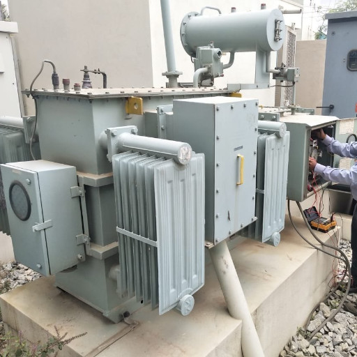
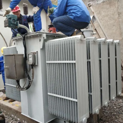
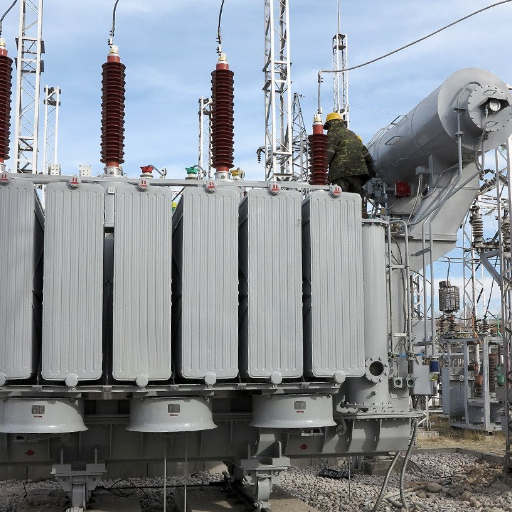
Transport, Unloading, and Positioning
The transformer is vulnerable to damage during transport and placement. Proper handling prevents core clamping looseness, winding displacement, and bushing damage that may not be visible but will cause failure under load.
Access Route Survey
Before delivery, survey the entire access route from the road to the installation site:
- Road width and weight limits (transformers on trailers can exceed 40 tons total)
- Turning radius at corners and gates
- Overhead clearance for cables and branches
- Ground bearing capacity for trailer parking and crane outriggers
- Bridge weight limits on the delivery route
Unloading Methods
Crane Placement: For large transformers or sites with limited access, use a mobile crane to lift the unit directly onto the pad. Verify crane capacity exceeds transformer weight plus rigging. Use spreader bars to prevent sling compression on the tank. Lift from manufacturer-designated lifting lugs only.
Roller/Skate Positioning: For smaller units on accessible sites, roll the transformer from the trailer to the pad using steel rollers or hydraulic skates. This method is gentler on the unit but requires a smooth, level path and sufficient space for maneuvering.
Shock Load Prevention
Transformers are designed for vertical static loads, not horizontal shocks. Avoid sudden stops, drops, or impacts during unloading. Impact accelerations exceeding 3g can loosen core clamping bolts, shift windings, and crack insulation structures. Use cushioned slings and controlled lowering speeds.
Leveling and Alignment
Once positioned on the pad, verify levelness in both longitudinal and transverse directions. Use steel shims under the transformer base to correct minor pad irregularities. Align bushings with cable trenches and ensure cooling radiators face unobstructed airflow paths. Confirm that the transformer nameplate is readable and oriented for easy access.
Electrical Connections and Grounding
Electrical connections and grounding determine safety, performance, and protection effectiveness. Errors in this phase create hazards that may not be apparent until the transformer is energized.
Cable Sizing and Routing
Size primary and secondary cables based on rated current, voltage drop limits, and fault current withstand. For a 1,000 kVA, 11/0.4 kV transformer, primary current is approximately 52 A and secondary current is approximately 1,440 A. Account for future load growth by selecting cables one size above minimum requirements.
Route cables in trenches with adequate bending radius. Standard power cable minimum bending radius is 12-15 times the cable outer diameter. Exceeding this radius causes insulation stress and premature failure. Maintain 300 mm minimum separation between HV and LV cables in shared trenches.
Bushing Connections
Connect primary and secondary conductors to bushings using manufacturer-specified torque values. Undertorqued connections overheat under load. Overtorqued connections damage bushing terminals. Use calibrated torque wrenches and follow the sequence in the installation manual. Apply conductive grease to aluminum-to-copper interfaces to prevent galvanic corrosion.
Grounding Electrode Design
Transformer grounding serves two purposes: system grounding (neutral connection) and equipment grounding (tank and enclosure). Both must be reliable.
Design the grounding electrode per IEEE 80 or IEC 61936-1:
- Target resistance: ≤5 ohms for distribution transformers; ≤1 ohm in some utility specifications
- Use copper-clad steel rods, copper conductors, or exothermic welded connections
- Install ground rods in a triangular or rectangular array around the transformer
- Connect the transformer tank, neutral terminal, cable armor, and surge arresters to the common grounding grid
- Test ground resistance after installation and before energization
Poor grounding creates touch potential hazards during internal faults. A worker touching an improperly grounded tank during a fault can receive a lethal shock even if the protection system operates correctly.
Lightning Protection
Install surge arresters on the primary side to protect against lightning and switching surges. Connect arresters directly to the tank grounding system with the shortest possible conductor length. Each additional meter of grounding conductor increases surge let-through voltage by approximately 1.5 kV during fast transients.
Fire Safety and Clearance Requirements
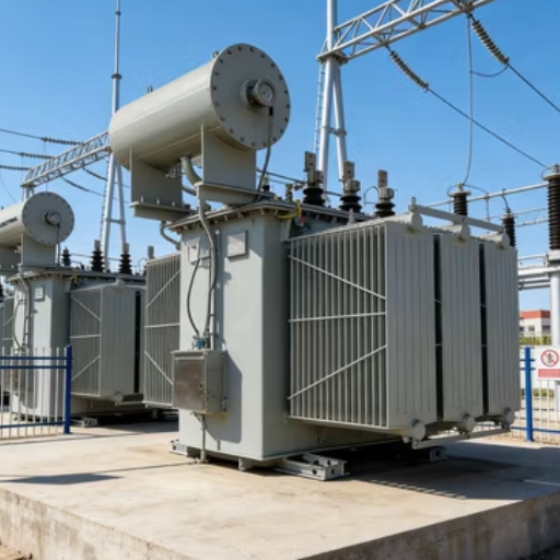
Oil-filled transformers contain flammable liquid. The installation layout must contain fire risk and protect adjacent structures.
Separation Distances
Minimum clearances depend on oil volume, fluid type, and local codes. For mineral oil-filled distribution transformers, typical requirements are:
| Condition | Minimum Clearance |
|---|---|
| Transformer to building (non-combustible) | 3 meters |
| Transformer to building (combustible) | 5-10 meters |
| Transformer to transformer | 3-5 meters |
| Transformer to property line | 3 meters |
| Transformer to vegetation | 3 meters |
Natural ester and synthetic ester fluids, with flash points above 300°C, may qualify for reduced separation distances under some codes. Verify local amendments before finalizing layout.
Fire Walls
Install fire-rated walls between multiple transformers or between transformers and critical structures when separation distances cannot be achieved. A 2-hour fire-rated wall extending 1 meter above the transformer profile is standard for medium-voltage installations.
Fire Suppression
Large substations may include automatic fire suppression:
- Water spray systems cool the tank and oil surface
- Foam systems suppress oil pool fires
- Nitrogen injection systems displace oxygen inside the tank during internal faults
For most outdoor distribution installations, proper separation and containment are sufficient without active suppression.
Oil Filling and Vacuum Drying
Oil immersed transformers rated 72.5 kV and above require vacuum drying before oil filling to remove moisture from insulation paper. This step is critical for long-term insulation integrity.
Oil Quality Verification
Before filling, test the oil for dielectric breakdown voltage, moisture content, and particulate contamination. New mineral oil should have a breakdown voltage ≥70 kV and moisture ≤10 ppm. Do not use oil that fails these thresholds.
Vacuum Drying Procedure
- Connect a vacuum pump to the transformer tank
- Pull vacuum to ≤1 mbar (absolute pressure)
- Hold vacuum for 24-72 hours depending on voltage class and unit size
- Monitor vacuum level; a rising pressure indicates ongoing moisture release
- When pressure stabilizes, break vacuum with dry nitrogen or oil vapor
Vacuum drying removes moisture from cellulose insulation that would otherwise reduce dielectric strength and accelerate aging. Skipping this step on high-voltage units is a common cause of early-life failures.
Oil Filling Sequence
Fill oil slowly through the bottom valve to minimize air entrainment. Fill to the manufacturer-specified level at ambient temperature. After filling, allow 12-24 hours for air bubbles to rise before performing dielectric tests.
For detailed oil testing procedures, see our transformer oil testing and maintenance guide.
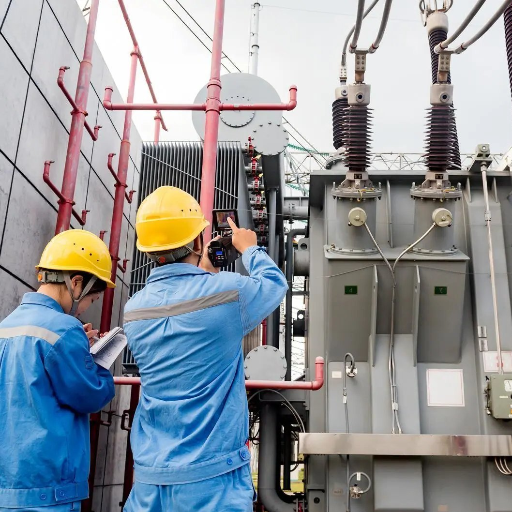
Pre-Energization Inspection Checklist
The pre-energization inspection catches installation errors before they become failures. Do not skip items to save schedule time.
Mechanical Inspection
- Oil level is correct for ambient temperature
- All valves are in the correct operating position
- No leaks at bushings, flanges, welds, or valves
- Conservator and breather are properly connected (conservator types)
- Pressure relief device unobstructed
- Cooling fans and pumps rotate freely
Electrical Inspection
- All bolted connections torqued to specification
- Phase rotation and polarity correct
- Grounding connections are complete and resistance verified
- Surge arresters installed and grounded
- Protection relay settings match the coordination study
- CT polarities verified
Control and Alarm Tests
- Temperature monitoring alarms and trips functional
- Buchholz relay tested (conservator types)
- Pressure relief alarm tested
- Cooling control sequences verified
- Remote monitoring signals confirmed
In 2021, a utility commissioning team in South America skipped the insulation resistance test on a 5 MVA substation transformer to meet an energization deadline. The unit had been stored outdoors during monsoon season before delivery. Moisture had entered through an improperly sealed shipping vent. The insulation resistance, had it been measured, would have shown 12 MΩ instead of the required 100 MΩ minimum. The transformer energized successfully and operated for 36 hours before an internal arc developed between the HV winding and core. The fault destroyed the unit and caused a 48-hour outage. The root cause was moisture. The immediate cause was skipping a 15-minute test.
Commissioning Tests
Commissioning tests establish baseline performance data and verify that the transformer meets specifications before entering service.
| Test | Purpose | Acceptance Threshold |
|---|---|---|
| Insulation resistance | Verify winding insulation integrity | ≥100 MΩ at 20°C |
| Transformer turns ratio (TTR) | Verify correct ratio and tap positions | Within 0.5% of nameplate |
| Winding resistance | Check conductor continuity | Balanced within 2% between phases |
| Dielectric breakdown voltage | Verify oil quality | ≥70 kV for new mineral oil |
| Oil moisture content | Verify dryness | ≤10 ppm for 72.5 kV+ |
| Dissolved gas analysis (DGA) | Establish baseline gas levels | Below IEEE C57.104 thresholds |
Record all test results in a permanent file. Future maintenance tests are compared against these baseline values. Any significant change indicates developing problems.
Common Installation Mistakes and How to Avoid Them
| Mistake | Cause | Prevention |
|---|---|---|
| Inadequate foundation | Skipping the geotechnical survey | Always assess soil bearing capacity before pad design |
| Incorrect grounding | Using undersized conductors or too few rods | Design per IEEE 80; test resistance before energization |
| Missing oil containment | Cost reduction or ignorance of regulations | Include containment in every outdoor oil-filled installation |
| Poor cable management | Exceeding the bending radius or insufficient separation | Follow cable manufacturer specifications; use dedicated trenches |
| Rushing pre-energization checks | Schedule pressure | Build commissioning time into the project timeline; skipping tests saves hours, not days |
| Improper vacuum drying | Time pressure on high-voltage units | Follow the manufacturer’s drying protocol; verify with insulation resistance |
| Wrong oil level | Filling at the wrong temperature | Use the temperature-compensated level chart from the manufacturer |
Frequently Asked Questions
How much space does an outdoor transformer need?
The installation footprint includes the transformer dimensions plus maintenance clearances. Allow 1-1.5 meters on radiator faces, 0.6-1 meter on non-radiator sides, and additional space for oil containment. A 1,000 kVA unit typically requires a 4×4 meter area including clearances.
What type of concrete is used for transformer pads?
Standard reinforced concrete with a minimum 25 MPa compressive strength is sufficient for most distribution transformers. Use sulfate-resistant cement in aggressive soil conditions. The surface should be smooth for transformer positioning but not polished and slippery.
How is a transformer anchored for earthquakes?
In seismic zones, anchor the transformer to the pad with bolts designed to withstand horizontal acceleration per IEEE 693. Flexible connections on oil pipes and cables prevent damage during ground motion. Verify the manufacturer provides seismic qualification for the design family.
Can a transformer be installed on an existing pad?
Yes, if the existing pad meets load-bearing, levelness, and dimensional requirements. Verify that the pad is structurally sound, level within tolerance, and properly drained. Old pads may have hidden cracks or corrosion that affect performance.
What is the minimum distance from a transformer to a building?
For mineral oil-filled transformers, minimum separation is 3 meters from non-combustible buildings and 5-10 meters from combustible structures, depending on oil volume and local codes. Natural ester transformers may allow reduced distances. Always verify local amendments.
How long does outdoor transformer installation take?
A standard distribution transformer installation requires 2-5 days: 1 day for site prep and positioning, 1 day for connections and grounding, 1-2 days for oil filling and drying (if required), and 1 day for testing and inspection. Large power transformers may require 7-14 days.
Do outdoor transformers need a fence?
Most jurisdictions require security fencing around outdoor transformers for public safety. Typical requirements are a 2-meter minimum height fence with lockable gates, located at least 1 meter outside the transformer footprint. Pad-mounted units in public areas require tamper-resistant enclosures.
What is the oil capacity of a typical distribution transformer?
Oil volume scales with kVA rating. A 500 kVA unit holds approximately 300-400 liters. A 2,500 kVA unit holds 1,000-1,500 liters. A 5 MVA unit holds 3,000-5,000 liters. Containment design must account for the full volume plus 10% margin.
Conclusion
Outdoor transformer installation is a multi-disciplinary process that combines civil engineering, electrical work, environmental protection, and quality verification. The transformer itself is only one component of a system that includes the foundation, containment, grounding, connections, and protection infrastructure.
Each phase builds on the previous one. A geotechnical survey informs pad design. Pad design determines anchoring and drainage. Drainage and containment satisfy environmental requirements. Environmental compliance enables permit approval. Permit approval allows energization. Skipping any step creates risk that compounds through the remaining phases.
The most expensive installation mistakes are not the visible ones. They are the invisible shortcuts: the soil test that was never done, the grounding resistance that was never measured, the insulation test that was skipped to save an afternoon. These omissions do not create immediate failures. They create vulnerabilities that surface months or years later, often at maximum cost and minimum convenience.
Plan the installation before the transformer ships. Verify every specification against the actual site conditions. Test everything before energization. And keep records that establish baselines for decades of future maintenance.