Oil Filled Transformer for Substation: Design Standards & Installation Guide
An oil-immersed transformer for substation service is the standard choice for electrical transmission and distribution networks, providing the efficiency, overload capacity, and voltage range needed to step power down from transmission levels to distribution voltages. Choosing the wrong rating, vector group, or cooling configuration for a substation can cause voltage instability, premature equipment failure, or project delays that cost far more than the transformer itself.
When the EPC team at DeltaGrid Consortium commissioned a 33/11 kV substation in Southeast Asia in 2023, they assumed any standard Dyn11 transformer would handle the load. They missed a critical detail: the substation served a mix of industrial three-phase motors and residential single-phase lighting. The Yyn0 vector group they initially accepted created a floating neutral under unbalanced conditions. Within six months, neutral current reached 45% of phase current, overheating the neutral bushing and causing repeated protection trips. The team spent $15,000 to replace bushings, reconfigure the grounding system, and install a proper Dyn11 unit. The transformer worked fine. The specification was wrong.
This guide covers how to specify, install, and commission an oil filled transformer for substation applications. You will learn voltage class selection, standards compliance, cooling design, foundation requirements, and the full commissioning workflow.
Key Takeaways
- Oil immersed transformers for substations typically handle 11 kV to 400 kV, with ratings from 1 MVA to over 100 MVA depending on grid level.
- Dyn11 is the most common vector group for distribution substations because it provides stable neutral grounding and handles unbalanced loads.
- ONAN cooling suits most distribution substations up to ~5 MVA; ONAF or OFAF is required for larger transmission substations.
- Foundation design must include oil containment holding 110% of total oil volume and seismic anchoring per local codes.
- Commissioning requires insulation resistance, turns ratio, dielectric, partial discharge, and oil quality tests before energization.
What Is a Substation Transformer?
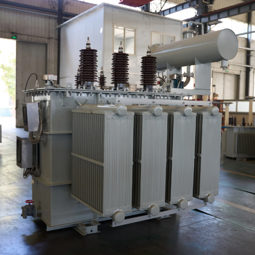
A substation transformer is an oil filled transformer installed within an electrical substation to transfer power between different voltage levels in a transmission or distribution network. Its primary role is stepping down high transmission voltages to medium distribution voltages, or stepping down medium voltages to low voltages for end users.
Oil-filled designs dominate substation applications because liquid insulation enables higher thermal performance and dielectric strength than air or solid insulation at equivalent ratings. A substation transformer must operate reliably under continuous load, tolerate short-duration overloads during peak demand, and withstand fault currents without structural damage. These requirements make the oil-immersed transformer for substation service the default technology for outdoor installations worldwide.
For a complete overview of oil-filled transformer technology, see our oil-filled transformer guide.
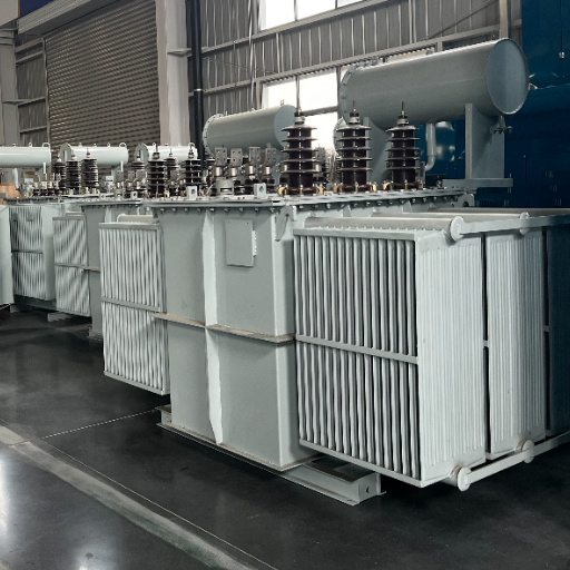
Why Substations Rely on Oil-Filled Designs
Substations demand high capacity, long service life, and proven reliability. Oil-filled transformers deliver all three. Liquid cooling allows compact designs at ratings above 2,500 kVA, where dry-type transformers become physically impractical. The established service infrastructure for oil testing, filtration, and reclamation makes maintenance predictable over a 25-40 year lifespan.
Substation Transformer Voltage Classes and Ratings
Substation transformers cover a wide voltage spectrum. Selecting the correct voltage class is the first step in specification.
| Substation Type | Primary Voltage | Secondary Voltage | Typical kVA Range | Application |
|---|---|---|---|---|
| Distribution | 11 kV or 33 kV | 400/230 V | 100 kVA – 5,000 kVA | Urban/rural distribution |
| Medium-voltage | 66 kV or 110 kV | 11 kV or 33 kV | 5 MVA – 40 MVA | Regional substations |
| Transmission | 220 kV or 400 kV | 66 kV or 110 kV | 50 MVA – 300 MVA+ | Grid interconnection |
| Solar/wind collection | 33 kV | 400 V – 690 V | 500 kVA – 3,500 kVA | Renewable step-up |
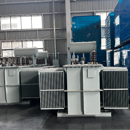
Distribution substations serving end users typically use 11 kV or 33 kV primary with 400 V secondary. Medium-voltage substations step transmission voltages down to distribution levels. Transmission substations handle bulk power transfer between grid regions.
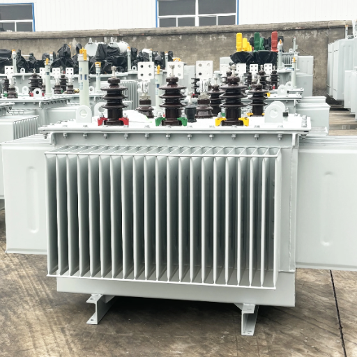
Shandong Electric Co., Ltd. manufactures oil-immersed transformers for substation applications from 50 kVA to 50 MVA, covering distribution through medium-power transmission levels.
For 11 kV specification details, see our 11kV oil filled transformer guide.
Design Standards and Compliance
Every oil-immersed transformer for substation service must comply with recognized international standards. Buyers should verify certification before accepting delivery.
Core Standards
- IEC 60076-1: General requirements for power transformers, including rating, tapping, and construction.
- IEC 60076-2: Temperature rise limits and thermal performance verification.
- IEC 60076-3: Insulation levels and dielectric test requirements.
- IEC 60076-5: Ability to withstand short circuit, requiring mechanical integrity under fault currents for 2 seconds.
- IEEE C57.12.00 / C57.12.90: North American general requirements and test codes.
Regional and Application-Specific Standards
- IEEE 693: Seismic design of electrical substations, required in earthquake-prone regions.
- IEC 61936-1: Safety requirements for power installations exceeding 1 kV AC, covering outdoor substation clearances and access.
- NFPA 70 / NEC Article 450: U.S. fire safety and installation requirements for liquid-filled transformers.
Manufacturers should provide type-test certificates from accredited laboratories such as KEMA, CESI, or UL for the design family. Routine tests on every unit should include winding resistance, turns ratio, no-load loss, load loss, and applied voltage tests.
Vector Group and Winding Configuration
The vector group defines how the primary and secondary windings connect and how their voltages relate in phase. For substation transformers, this choice affects grounding, harmonic handling, and parallel operation.
Common Vector Groups for Substations
| Vector Group | Primary Connection | Secondary Connection | Phase Shift | Best For |
|---|---|---|---|---|
| Dyn11 | Delta | Start with neutral | 330° (11 o’clock) | Distribution with mixed loads |
| YNd11 | Start with neutral | Delta | 330° | Transmission step-down |
| YNyn0 | Start with neutral | Start with neutral | 0° | Special grounding schemes |
Dyn11 is the default choice for distribution substations. The delta primary traps third-harmonic currents, while the star secondary with accessible neutral provides stable grounding for single-phase loads. This configuration handles unbalanced loads without excessive neutral displacement.
YNd11 is common in transmission substations where the primary side requires solid grounding and the secondary feeds into a delta-connected distribution network.
Selection Criteria
Specify the vector group based on:
- Load characteristics: Mixed single-phase and three-phase loads favor Dyn11.
- Grounding philosophy: Solid grounding requires star-connected windings with a neutral.
- Parallel operation: Transformers operating in parallel must share the same vector group and impedance.
- Harmonic environment: Delta windings absorb triplen harmonics from nonlinear loads.
Tap Changer Requirements for Substations
Voltage in a substation fluctuates with load, grid conditions, and generation availability. Tap changers adjust the transformer turns ratio to maintain secondary voltage within acceptable limits.
On-Load Tap Changer (OLTC)
An OLTC adjusts taps while the transformer is energized and carrying a load. This is essential for substations where voltage must remain stable during daily load cycles. Standard tap ranges provide +/- 10% adjustment in 1.25% or 1.5% steps. OLTC mechanisms require regular maintenance, including contact inspection and oil replacement, typically every 5-7 years depending on operation frequency.
Off-Circuit Tap Changer
Off-circuit tap changers require de-energization to adjust. They are suitable for substations where voltage variation is seasonal or predictable, and where taking the transformer offline for adjustment is acceptable. First cost is lower than OLTC, but operational flexibility is reduced.
Specification Guidance
Specify OLTC for:
- Urban distribution substations with high daily load variation
- Substations supplying sensitive industrial loads
- Grid interconnection points where voltage regulation is critical
Off-circuit taps are acceptable for:
- Rural substations with predictable seasonal loads
- Backup or standby transformers
- Projects with tight capital budgets and low load variability
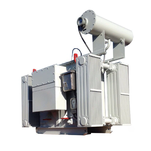
Cooling Configurations for Substation Service
Cooling determines how much heat the transformer can dissipate, which directly limits continuous rating and overload capability. Substation transformers use several standardized cooling modes.
| Cooling Mode | Code | Description | Typical Substation Application |
|---|---|---|---|
| Oil Natural, Air Natural | ONAN | Natural convection, no fans or pumps | Distribution substations up to ~5 MVA |
| Oil Natural, Air Forced | ONAF | Natural oil flow, forced air over radiators | Medium substations, ~5-20 MVA |
| Oil Forced, Air Forced | OFAF | Forced oil circulation and air cooling | Large transmission substations |
| Oil Directed, Air Forced | ODAF | Directed oil flow through windings | Extra-high-voltage units |
ONAN is the default for distribution substations. It requires no moving parts, minimizing maintenance and failure points. A 2,500 kVA ONAN unit in a 30°C ambient environment operates comfortably within IEC 60076-2 temperature rise limits.
ONAF extends the rating by 20-30% without increasing the transformer size. Fans mounted on radiators force additional air across cooling surfaces. This is valuable when space constraints prevent installing a larger ONAN unit.
OFAF and ODAF serve large transmission substations where power densities are high and natural convection cannot remove sufficient heat. These systems require pumps, fans, and control circuits with associated maintenance needs.
Bushings, Cable Boxes, and Terminal Arrangements
Bushings provide the insulated path for electrical conductors through the transformer tank wall. Cable boxes organize and protect secondary connections. Both must match the substation cable routing and protection scheme.
Bushing Types
- Oil-immersed bushings: Used at lower voltages (up to 52 kV), simple and reliable.
- Condenser bushings: Used at higher voltages (72.5 kV and above), with graded capacitance to control electric field distribution.
- Composite bushings: Lighter than porcelain, resistant to vandalism and pollution, increasingly common in outdoor substations.
Cable Box Configurations
Bottom-entry cable boxes are standard for pad-mounted and ground-mounted substation transformers. Side-entry configurations accommodate installations where cable trenches run at transformer level. CT chambers for metering current transformers are often integrated into the cable box on the secondary side.
Maintenance Clearance
Bushings require sufficient clearance for hot-line washing, replacement, and inspection. IEC 61936-1 defines minimum phase-to-phase and phase-to-earth clearances by voltage class. Design the substation layout with at least 0.5 meters of additional clearance beyond the minimum for safe maintenance access.
Foundation and Oil Containment Design
A substation transformer foundation must support the unit weight, contain the full oil volume in case of rupture, and resist seismic forces. Poor foundation design is a common source of substation transformer failure and environmental incidents.
Concrete Pad Requirements
The pad must be level within 3 mm per meter to prevent oil level imbalances and bushing stress. Reinforced concrete design must support the transformer dead weight plus oil volume, typically 1.5-3.0 tons for distribution units and 20-50 tons for medium-power units. Allow for dynamic loads during transport and seismic events.
Oil Containment
Regulations require containment systems capable of holding 110% of the total oil volume. Common designs include:
- Bund walls: Concrete walls surrounding the pad, simple and effective.
- Collection pits: Underground pits with oil-water separation for outdoor substations.
- Double-wall tanks: Integrated containment for pad-mounted units.
The containment system must prevent oil from reaching soil, groundwater, or storm drains. Install an oil alarm or level sensor for early leak detection.
Seismic Anchoring
In seismic zones, anchor the transformer to the foundation with bolts designed to withstand horizontal acceleration per IEEE 693. Flexible connections on oil pipes and cables prevent damage during ground motion. Verify that the manufacturer provides seismic qualification certificates for the design family.
Cable Trenches
Route primary and secondary cables in trenches with adequate bending radius for the cable type. Maintain separation between high-voltage and low-voltage cables per local electrical codes. Provide drainage to prevent water accumulation.
When the utility operator in Eastern Europe expanded a 110/33 kV substation in 2022, they treated oil containment as a standard civil works item and accepted the lowest contractor bid without engineering review. The containment pit liner was installed with an inadequate overlap at the seam. During commissioning, a minor bushing leak from transport damage released approximately 200 liters of oil. The liner seam failed, and oil seeped into the gravel sub-base. Remediation required removing 80 cubic meters of contaminated material, installing a new liner, and delaying energization by 22 days. The civil works savings of 3,000costtheproject3,000costtheproject47,000 in remediation and delay penalties.
For detailed outdoor foundation and installation guidance, see our outdoor transformer installation guide.
Fire Protection and Safety in Substations
Oil filled transformers contain flammable liquid, which creates fire risk if an internal fault causes rapid oil heating and ignition. Substation design must mitigate this risk through separation, containment, and suppression.
Separation Distances
IEC 61936-1 specifies minimum distances between transformers and between transformers and substation boundaries. For mineral oil-filled units, typical separation is 5-10 meters depending on voltage and oil volume. Natural ester fluids, with flash points above 300°C, may allow reduced separation distances under some local codes.
Fire Walls
Fire-rated walls between transformers limit radiant heat transfer during a fire event. A 2-hour fire rating is common for medium-voltage substations. Fire walls must extend beyond the transformer profile and terminate in fire-rated barriers.
Suppression Systems
Large substations often include automatic fire suppression:
- Water spray systems: Cool the tank and oil surface, preventing ignition or reignition.
- Foam systems: Smother oil fires with foam blankets.
- Nitrogen injection: Some designs inject nitrogen into the tank to displace oxygen during internal faults.
NEC 450 and NFPA 70 Requirements
In the United States, NEC Article 450 specifies installation requirements for liquid-filled transformers, including vault construction for indoor units, oil containment, and clearances. Outdoor substations must comply with NFPA 70 and local amendments.
Natural ester and synthetic ester fluids reduce fire risk significantly. Some jurisdictions allow reduced containment and separation requirements when less-flammable fluids are used. Verify local amendments before finalizing substation layout.
For a comparison of transformer fluids and their fire safety ratings, see our transformer oil types guide.
Substation Transformer Installation Workflow
Installing an oil immersed transformer for substation service follows a structured workflow from site preparation to pre-energization inspection.
Step 1: Site Preparation and Pad Construction
Excavate and form the concrete pad to the manufacturer’s dimensional requirements. Install containment systems, drainage, and cable trenches before pouring concrete. Allow 28 days for concrete curing before placing transformer weight. Verify pad levelness with a precision level.
Step 2: Transport and Unloading
Coordinate delivery with a heavy-lift contractor. Check access roads, turning radius, and ground bearing capacity along the delivery route. Use spreader bars and slings rated for the transformer weight. Avoid shock loads that can damage core clamping or bushings.
Step 3: Positioning and Leveling
Roll or crane the transformer onto the pad. Align bushings with cable trenches and cooling equipment with prevailing wind direction where possible. Level the unit within manufacturer tolerances using steel shims. Check oil level in the main tank and conservator.
Step 4: Oil Filling and Vacuum Drying
If the transformer was shipped without oil or with reduced oil, fill per manufacturer instructions. Vacuum drying removes moisture from insulation paper before oil introduction. This step is critical for units rated 72.5 kV and above. Maintain vacuum levels and drying time per the factory protocol.
Step 5: Bushing and Cable Connection
Install bushings if they were shipped separately. Connect primary and secondary cables with proper torque on bolted terminals. Verify phase rotation and polarity. Install surge arresters on the primary side for lightning protection.
Step 6: Control and Protection Wiring
Connect cooling fan controls, temperature monitors, Buchholz relays, pressure relief devices, and tap changer drives to the substation control system. Test all alarm and trip functions before energization.
Step 7: Pre-Energization Inspection
Walk through the complete installation checklist:
- Oil level correct at ambient temperature
- All valves in correct position
- Cooling fans rotate freely and in correct direction
- No leaks at bushings, flanges, or valves
- Grounding connections complete and resistance verified
- Protection relay settings match coordination study
- Phase labels correct and visible
Commissioning Tests and Acceptance Criteria
Commissioning verifies that the oil immersed transformer for substation service meets design specifications and is safe to energize. Do not skip tests to save schedule time.
| Test | Purpose | Acceptance Criteria | Standard Reference |
|---|---|---|---|
| Insulation resistance | Verify winding insulation integrity | ≥100 MΩ at 20°C | IEEE C57.12.90 |
| Transformer turns ratio (TTR) | Verify correct turns ratio and tap positions | Within 0.5% of nameplate | IEEE C57.12.90 |
| Winding resistance | Check conductor continuity and connections | Balanced within 2% between phases | IEEE C57.12.90 |
| Applied voltage test | Verify insulation strength to ground | No breakdown at specified voltage | IEC 60076-3 |
| Induced voltage test | Verify insulation strength between turns | No partial discharge escalation | IEC 60076-3 |
| Partial discharge | Detect internal voids or defects | <100 pC (170 kV class), <300 pC (72.5 kV class) | IEC 60076-3 |
| Oil dielectric breakdown voltage | Verify oil quality | ≥70 kV for new mineral oil | IEC 60156 |
| Oil moisture content | Verify dryness | ≤10 ppm for 170 kV class | IEC 60814 |
| Dissolved gas analysis (DGA) | Establish baseline gas levels | Below IEEE C57.104 threshold levels | IEEE C57.104 |
| Functional tests | Verify accessories and controls | Fans, pumps, relays, tap changer operate correctly | Manufacturer protocol |
Perform oil sampling before energization to establish a baseline for future DGA trending. Any significant gas content before load indicates a manufacturing or transport issue requiring investigation.
Partial discharge testing is particularly important for resin-impregnated paper (RIP) or oil-impregnated paper (OIP) bushings and for units rated 72.5 kV and above. Elevated partial discharge levels indicate insulation defects that will worsen under operating voltage stress.
For detailed oil testing procedures and maintenance schedules, see our transformer oil testing and maintenance guide.
Substation Transformer Maintenance Planning
A substation transformer operates for decades. A structured maintenance plan prevents unplanned outages and extends service life.
Annual Inspection
- Visual check for oil leaks, corrosion, and paint damage
- Silica gel breather condition (conservator types)
- Oil level verification
- Cooling fan and pump operation
- Thermograph survey of bushings, terminals, and cable connections
- Protection relay and alarm function tests
Biennial Oil Testing
- Dielectric breakdown voltage
- Moisture content (Karl Fischer)
- Acidity
- Interfacial tension
- Color and visual appearance
Five-Year Major Maintenance
- OLTC inspection and contact replacement if worn
- Bushing capacitance and power factor testing
- Winding insulation power factor
- Core ground test
- Oil filtration or replacement if degraded
Keep all test records in a trending database. DGA trend analysis detects incipient faults months before they cause failure. A stable transformer shows minimal gas generation year over year. Rapid increases in hydrogen, methane, or acetylene indicate developing internal problems.
Frequently Asked Questions
What kVA rating do I need for a substation transformer?
Calculate based on connected load, diversity factor, and future growth. For a distribution substation serving 2,000 residential customers, typical demand is 1.5-2.5 kVA per customer with a diversity factor of 0.3-0.4. A 1,500 kVA transformer often suffices. Industrial substations require load analysis including motor starting currents and power factor. Size for 20-30% growth over 10 years.
How far should a substation transformer be from buildings?
Separation depends on oil volume, fluid type, and local codes. Mineral oil transformers typically require 5-10 meters from buildings. Natural ester transformers may allow reduced separation due to higher flash point. Always verify local amendments to NFPA 70, IEC 61936-1, or national equivalents.
What is the difference between indoor and outdoor substation transformers?
Outdoor substation transformers are the standard configuration, installed on concrete pads with weatherproof enclosures and cooling radiators exposed to ambient air. Indoor substation transformers require vaults with fire containment, ventilation, and oil drainage systems per NEC Article 450. Indoor installation is rare except in dense urban areas where land cost justifies the vault construction.
Can natural ester be used in large substation transformers?
Yes. Natural ester has been used in transformers up to several hundred MVA. The main considerations are viscosity at low temperature, which affects cooling performance in cold climates, and compatibility with gaskets and seals. Most modern transformer designs accept natural ester without modification.
How long does substation transformer commissioning take?
Commissioning typically requires 3-7 days for distribution substations and 7-14 days for transmission substations. Timeline depends on voltage class, accessories, and whether oil filling and vacuum drying are performed on site. Delays usually come from incomplete civil works or missing test equipment, not from the tests themselves.
What causes substation transformer failure?
The leading causes are insulation aging, moisture ingress, overloading, and lightning or switching surges. DGA and oil testing detect most of these conditions before failure. Bushings and tap changers are the most frequent external failure points.
Is a conservator or hermetically sealed design better for substations?
Conservator-type transformers dominate utility substations because oil sampling and maintenance are straightforward. Hermetically sealed designs suit remote or unmanned substations where maintenance access is limited. For manned urban substations, conservator designs are usually preferred.
For a detailed comparison of sealed designs, see our hermetically sealed transformer guide.
What standards should a substation transformer meet for export?
Specify IEC 60076 compliance for global markets. North American projects require IEEE C57 certification. The Middle East often requires IEC with additional environmental testing for high temperature and dust. African and Southeast Asian markets may accept IEC or equivalent national standards. Always confirm the destination country’s grid code and import requirements before specification.
Conclusion
An oil immersed transformer for substation service is a long-term infrastructure investment that must match the voltage class, load profile, and environmental conditions of its installation. The specification process is not simply selecting a kVA rating from a catalog. It requires choosing the right vector group for load characteristics, the right cooling mode for ambient conditions, the right tap changer for voltage regulation needs, and the right fluid for fire safety and environmental requirements.
Foundation design, oil containment, and fire protection are as important as the transformer itself. A well-specified unit on a poorly designed foundation will fail prematurely. A properly installed transformer without commissioning tests may harbor manufacturing defects that surface under load.
When the engineering team at SolarFields Development planned a 50 MW solar farm substation in North Africa, they initially specified standard ONAN cooling for a 3.15 MVA step-up unit. The local EPC contractor noted that summer ambient temperatures reached 48°C and that the site experienced frequent dust storms. The team revised the specification to ONAF with filter-equipped fan enclosures and added a natural ester fill to handle the thermal stress and reduce fire risk near the control building. The unit has operated for three years without a single cooling alarm or oil quality issue. The revised specification added 8% to upfront cost. It eliminated the risk of summer derating and unplanned outages.
Start your substation transformer specification with the grid voltage, load forecast, and installation environment. Define the standards your market requires. Verify manufacturer capability through type-test certificates and reference projects. And test thoroughly before energization.
Ready to specify an oil immersed transformer for your substation project? Send us your single-line diagram, voltage levels, kVA requirements, and site conditions. Our engineering team will review your specification, recommend the optimal design, and provide a detailed quotation with lead time and certification documentation.