11kV and 33kV Oil Immersed Transformer: Specifications and Selection Guide
An 11kV oil-immersed transformer is the standard distribution voltage class for utility grids, industrial plants, and commercial installations across Europe, Africa, Asia, and Australia. A 33kV oil-immersed transformer serves the next tier: medium-voltage distribution networks, rural grids, wind farms, and substation step-down applications. Choosing the wrong voltage class, kVA rating, or efficiency tier can cause grid connection rejection, excessive operating costs, or premature equipment failure.
In 2023, a North African solar power developer commissioned a 50 MW photovoltaic power plant equipped with 30 1600 kVA step-up transformers. The developer initially assumed the local grid could accept an output voltage of 11 kV, common in many markets. However, during a review by the power company, the grid connection agreement explicitly stated that the only acceptable medium-voltage level for the substation was 33 kV. All the transformers had been ordered as 11/0.69 kV. The developer faced a choice: either spend $180,000 to replace all 30 transformers or build a separate 33/11 kV substation, complete with additional switchgear and land. They chose to build the substation. The project was successfully connected to the grid, but the budget exceeded the target by $180,000, and the commercial operation date was delayed by eight weeks. The transformers themselves were not the problem; the issue lay in the specifications.
This guide covers the complete specifications for 11kV and 33kV oil immersed transformers. You will learn voltage class selection, standard ratings, efficiency classes, loss evaluation, and how to specify the right unit for your application.
Key Takeaways
- 11kV transformers typically serve distribution networks with ratings from 100 kVA to 5,000 kVA; 33kV transformers serve medium-voltage grids with ratings from 500 kVA to 20,000 kVA.
- Dyn11 is the standard vector group for both voltage classes because it provides stable neutral grounding and handles unbalanced loads.
- Standard impedance is 4-6% for 11kV distribution and 6-10% for 33kV step-down; higher impedance limits short-circuit current but increases voltage drop.
- Efficiency class selection (IEC Tier 2, DOE Tier, GB 20052) affects total cost of ownership more than purchase price over a 25-year service life.
- Type-test certificates from accredited laboratories (KEMA, CESI, UL) verify that the design family meets standards; routine tests on every unit verify individual performance.
What Is an 11kV Oil Immersed Transformer?
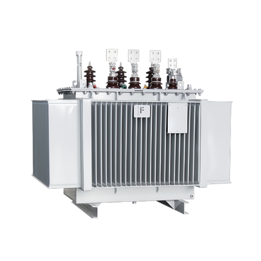
An 11kV oil immersed transformer is a liquid-filled electrical device that steps voltage down from 11,000 volts to low-voltage levels (typically 400/230 volts) for end-user distribution. It is the most common distribution transformer voltage class outside North America.
Standard Ratings
11kV transformers typically cover:
- Distribution range: 100 kVA to 5,000 kVA
- Primary voltage: 11 kV (with tap changers for +/- 5% or +/- 10% adjustment)
- Secondary voltage: 415/240 V or 400/230 V (three-phase four-wire)
- Cooling: ONAN standard; ONAF for ratings above 2,500 kVA
Common Applications
- Urban and suburban distribution networks
- Industrial plant main substations
- Solar farm step-up (from 400-800 V inverter output to 11 kV collection)
- Commercial building supply
- Rural electrification projects
For a complete overview of oil filled transformer technology and sub-types, see our oil filled transformer guide.
What Is a 33kV Oil Immersed Transformer?
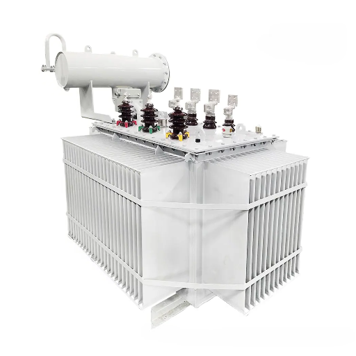
A 33kV oil immersed transformer steps voltage down from 33,000 volts to either 11,000 volts (for further distribution) or directly to 400/230 volts (for large industrial consumers). It operates at a higher voltage class than standard distribution, requiring larger clearances, higher insulation levels, and more robust bushing designs.
Standard Ratings
33kV transformers typically cover:
- Distribution range: 500 kVA to 20,000 kVA
- Primary voltage: 33 kV (with tap changer adjustment)
- Secondary voltage: 11 kV or 415/240 V
- Cooling: ONAN or ONAF depending on rating and ambient conditions
Common Applications
- Rural and semi-urban distribution (longer lines, lower load density)
- Wind farm collection and step-up
- Medium-voltage substations
- Large industrial consumers with direct 33 kV connection
- Grid interconnection points
11kV vs 33kV: When to Choose Which
The grid connection voltage at your project site determines which class you need. This is not a discretionary choice.
| Selection Factor | 11kV Transformer | 33kV Transformer |
|---|---|---|
| Grid connection | 11 kV distribution network | 33 kV medium-voltage network |
| Typical load density | High (urban, industrial) | Low to medium (rural, remote) |
| Maximum practical distance | 5-10 km from substation | 15-30 km from substation |
| Standard kVA range | 100-5,000 kVA | 500-20,000 kVA |
| Infrastructure cost | Lower (smaller conductors, simpler switchgear) | Higher (larger conductors, higher-rated switchgear) |
| Typical application | Urban distribution, solar farms, factories | Rural grids, wind farms, large substations |
When the grid utility specifies a connection voltage, that specification is final. Do not attempt to negotiate a lower voltage to reduce equipment cost. The cost difference between 11kV and 33kV transformers is typically 15-30% for equivalent kVA ratings. The cost of adding voltage conversion equipment or renegotiating a connection agreement exceeds the transformer savings by an order of magnitude.
For substation-specific design guidance that includes voltage class selection, see our oil filled transformer for substation guide.
Standard Specifications for 11kV Transformers
The following specifications apply to standard 11/0.415 kV, Dyn11, ONAN-cooled oil immersed transformers per IEC 60076-1.
11kV Transformer Specification Table
| Rating (kVA) | No-Load Loss (W) | Load Loss @ 75°C (W) | Impedance (%) | Weight (kg) | Oil Volume (L) | Dimensions L×W×H (mm) |
|---|---|---|---|---|---|---|
| 100 | 180 | 1,500 | 4.0 | 550 | 120 | 1,100×700×1,200 |
| 250 | 320 | 2,800 | 4.0 | 900 | 220 | 1,400×850×1,350 |
| 500 | 520 | 4,500 | 4.5 | 1,500 | 380 | 1,700×1,000×1,500 |
| 1,000 | 850 | 7,500 | 5.0 | 2,500 | 650 | 2,100×1,200×1,800 |
| 1,500 | 1,100 | 10,500 | 5.0 | 3,200 | 850 | 2,300×1,350×1,900 |
| 2,000 | 1,350 | 13,000 | 5.5 | 4,000 | 1,050 | 2,500×1,450×2,000 |
| 2,500 | 1,600 | 15,500 | 5.5 | 4,800 | 1,250 | 2,700×1,550×2,100 |
Values are typical for IEC 60076-1 standard efficiency class. Actual values vary by manufacturer design and efficiency tier. Always verify with the manufacturer for critical projects.
Insulation Levels
| Parameter | 11kV Winding |
|---|---|
| Highest voltage for equipment (Um) | 12 kV |
| Power frequency withstand (1 min) | 28 kV rms |
| Lightning impulse withstand (BIL) | 75 kV peak |
Vector Group
Dyn11 is standard for 11kV distribution transformers. The delta primary traps third-harmonic currents and provides a stable phase shift. The star secondary with accessible neutral supports single-phase loads and solid grounding. Specify Yyn0 only if your application explicitly requires it and you understand the neutral loading limitations.
Standard Specifications for 33kV Transformers
33kV transformers operate at higher insulation levels and typically handle larger kVA ratings than 11kV units.
33kV Transformer Specification Table
| Rating (kVA) | Voltage Ratio | No-Load Loss (W) | Load Loss @ 75°C (W) | Impedance (%) | Weight (kg) | Oil Volume (L) |
|---|---|---|---|---|---|---|
| 500 | 33/0.415 kV | 600 | 5,500 | 6.0 | 2,200 | 550 |
| 1,000 | 33/11 kV | 950 | 9,000 | 6.5 | 3,500 | 850 |
| 2,500 | 33/11 kV | 1,700 | 16,000 | 7.0 | 6,500 | 1,500 |
| 5,000 | 33/11 kV | 2,800 | 27,000 | 7.5 | 10,500 | 2,500 |
| 10,000 | 33/11 kV | 4,500 | 45,000 | 8.0 | 17,000 | 4,000 |
Values are typical for standard efficiency class. Higher efficiency tiers reduce both no-load and load losses at increased initial cost.
Insulation Levels
| Parameter | 33kV Winding |
|---|---|
| Highest voltage for equipment (Um) | 36 kV |
| Power frequency withstand (1 min) | 70 kV rms |
| Lightning impulse withstand (BIL) | 170 kV peak |
Bushings
11kV transformers typically use porcelain or composite oil-immersed bushings. 33kV transformers require condenser-type bushings with graded capacitance to manage the higher electric field stress. Composite bushings are increasingly common for both voltage classes due to lighter weight and better pollution performance.
Efficiency Classes and Loss Evaluation
Efficiency standards govern maximum allowable losses for oil immersed transformers. Selecting the right efficiency class is one of the most financially significant decisions in transformer procurement.
IEC 60076-1 Efficiency Classes
IEC defines three efficiency tiers based on no-load and load loss limits. Most markets now require minimum compliance with the middle tier. Premium efficiency reduces losses further at higher initial cost.
Regional Efficiency Requirements
| Region | Standard | Requirement |
|---|---|---|
| European Union | Commission Regulation 548/2014 (EcoDesign Tier 2) | Maximum losses for transformers placed on EU market |
| United States | DOE 10 CFR Part 431 | Minimum efficiency for liquid-immersed distribution transformers |
| China | GB 20052 | Three efficiency levels (1, 2, 3) with Level 1 being most efficient |
| International | IEC 60076-1 | Reference loss values (not mandatory) |
Total Cost of Ownership
When a procurement manager at an industrial park in Southeast Asia selected 11kV transformers for a new manufacturing facility in 2022, he compared three suppliers on purchase price alone. The lowest bid was 28,000forfour1,000kVAunits.Thehighestbidwas28,000forfour1,000kVAunits.Thehighestbidwas34,000. The difference was efficiency class: the low bidder met minimum GB Level 3 requirements; the high bidder offered GB Level 1 with 25% lower no-load losses and 15% lower load losses.
Over 20 years at 75% average load and 0.12perkWh,theLevel3unitswouldconsumeapproximately0.12perkWh,theLevel3unitswouldconsumeapproximately145,000 in losses. The Level 1 units would consume 108,000.The108,000.The6,000 purchase premium saved $37,000 in electricity. The procurement manager had optimized for capital expenditure. The real cost driver was operating expenditure.
Loss Evaluation Formula
Evaluate transformer options using:
Total Cost = Purchase Price + (No-Load Loss × Hours × Electricity Rate × Years) + (Load Loss × Load Factor² × Hours × Electricity Rate × Years)
Where:
- Hours = 8,760 per year
- Load Factor = average load / rated load (typically 0.5-0.8)
- Years = expected service life (20-25)
Use this formula to compare bids with different efficiency levels on equal terms.
Tap Changer Specifications
Voltage in distribution networks fluctuates with load, generation, and grid conditions. Tap changers adjust the transformer turns ratio to maintain secondary voltage within acceptable limits.
Off-Circuit Tap Changer
Standard for most 11kV and 33kV distribution transformers:
- Adjustment range: +/- 2.5% or +/- 5% (typically 3 steps: -5%, 0%, +5%)
- Requires de-energization to adjust
- Lower cost, lower maintenance
- Suitable for seasonal voltage variation
On-Load Tap Changer (OLTC)
Required for applications with high daily load variation or critical voltage stability:
- Adjustment range: +/- 10% in 1.25% or 1.5% steps
- Adjusts while energized and loaded
- Higher cost, requires periodic maintenance (typically every 5-7 years)
- Essential for substation transformers and grid interconnection points
Specification Guidance
Specify OLTC for:
- Utility substation transformers
- Industrial plants with sensitive equipment
- Grid-connected renewable energy projects
- Any application where voltage variation exceeds +/- 5% regularly
Off-circuit taps are sufficient for:
- Standard distribution transformers in stable grids
- Backup or standby units
- Projects with tight capital budgets and predictable loads
Bushings and Terminal Arrangements
Bushings provide the insulated path for electrical conductors through the transformer tank wall. Terminal arrangements organize primary and secondary connections.
11kV Bushings
- Type: Oil-immersed or composite
- Creepage distance: 240-320 mm (depending on pollution level)
- Current rating: 200-800 A depending on transformer kVA
- Configuration: Three HV bushings in line or triangular arrangement
33kV Bushings
- Type: Condenser-type or RIP (resin-impregnated paper)
- Creepage distance: 600-900 mm (depending on pollution level)
- Current rating: 200-1,250 A depending on transformer kVA
- Configuration: Three HV bushings, often with larger spacing than 11kV
Cable Boxes
Bottom-entry cable boxes are standard for both voltage classes. Side-entry arrangements accommodate installations where cable trenches run at transformer pad level. Integrate CT chambers on the secondary side for metering current transformers when required by the utility.
Weight, Dimensions, and Transport
Transport and handling constraints often drive transformer selection as much as electrical requirements.
Transport Considerations
- Road weight limits: Check maximum axle loads on the delivery route
- Bridge capacity: Verify all bridges on the access route
- Turning radius: Large transformers on trailers require wide turning areas
- Crane access: For units above 5 tons, verify crane capacity and pad loading
Standard Dimensions
A 1,000 kVA 11/0.415 kV transformer typically measures 2,100 × 1,200 × 1,800 mm (L×W×H) without radiators. Radiators add 400-800 mm to length. Always confirm exact dimensions with the manufacturer before designing the foundation and access route.
For detailed installation guidance including foundation design and crane requirements, see our outdoor transformer installation guide.
Standards and Certifications
Every 11kV and 33kV oil immersed transformer must comply with recognized standards. Request documentation before accepting delivery.
Core Standards
- IEC 60076-1: General requirements, ratings, and construction
- IEC 60076-2: Temperature rise and thermal performance
- IEC 60076-3: Insulation levels and dielectric tests (11kV: 28 kV AC, 75 kV BIL; 33kV: 70 kV AC, 170 kV BIL)
- IEC 60076-5: Short-circuit withstand (2-second duration)
- IEEE C57.12.00 / C57.12.90: North American requirements and test codes
Type Tests vs Routine Tests
Type tests verify the design family and are performed once per design:
- Temperature rise test
- Lightning impulse test
- Short-circuit withstand test
- Sound level measurement
Routine tests verify every individual unit:
- Winding resistance measurement
- Transformer turns ratio (TTR)
- No-load loss and current measurement
- Load loss and impedance measurement
- Applied voltage test
- Induced voltage test
- Oil tests (dielectric breakdown, moisture)
Request type-test certificates from accredited laboratories (KEMA, CESI, UL, CPRI) for the design family. Confirm that routine tests are performed on every unit in the manufacturer’s own test bay.
How to Specify and Procure
Use this specification checklist when requesting quotations for 11kV or 33kV oil immersed transformers.
Electrical Specification
| Parameter | Your Requirement | Notes |
|---|---|---|
| Rated power (kVA) | Include 20-30% future growth | |
| Primary voltage (kV) | 11 or 33 | Match grid connection agreement |
| Secondary voltage (kV) | 0.415 or 11 | Depends on downstream network |
| Vector group | Dyn11 (standard) | Specify YNd11 for 33/11 kV |
| Impedance (%) | 4-6% (11kV), 6-10% (33kV) | Higher limits fault current |
| Tap changer | Off-circuit or OLTC | OLTC for variable load |
| Cooling | ONAN or ONAF | ONAF for ratings >2,500 kVA |
| Frequency | 50 Hz or 60 Hz | Match local grid |
Efficiency and Losses
| Parameter | Your Requirement |
|---|---|
| Efficiency standard | IEC / DOE / GB / EcoDesign Tier 2 |
| Maximum no-load loss | (W) |
| Maximum load loss | (W) |
| Loss evaluation period | 20-25 years typical |
Physical and Environmental
| Parameter | Your Requirement |
|---|---|
| Ambient temperature max | (°C) |
| Altitude | (m above sea level) |
| Pollution level | Light / Medium / Heavy |
| Seismic zone | Per IEEE 693 or local code |
| Installation | Outdoor / Indoor vault |
Documentation Requirements
- Type-test certificates from accredited lab
- Routine test reports for every unit
- Oil quality certificates (new oil)
- Material certificates for copper and core steel
- Compliance declaration for specified standards
When an EPC contractor in Eastern Europe specified 33/11 kV transformers for a substation upgrade in 2021, he copied the impedance value (6%) from a previous 11kV project without recalculating for the new voltage class and grid configuration. The 33kV grid had lower short-circuit capacity than expected. The 6% impedance allowed fault currents that exceeded the rating of the existing 11kV switchgear downstream. The contractor had to add current-limiting reactors at $8,000 each or replace the switchgear. A 7.5% impedance specification would have eliminated the problem at zero additional transformer cost.
Frequently Asked Questions
What is the difference between 11kV and 33kV transformers?
11kV transformers step down to 400/230 V for end-user distribution. 33kV transformers either step down to 11kV for further distribution or directly to 400/230 V for large consumers. The primary difference is insulation level (11kV: 75 kV BIL; 33kV: 170 kV BIL), physical size, and cost. Grid connection voltage determines which you need.
How do I calculate the right kVA rating?
Sum all connected loads, apply a diversity factor (typically 0.6-0.8 for mixed loads), and add 20-30% for future growth. For a factory with 800 kW of motors and 200 kW of lighting at 0.85 power factor: (1,000 kW / 0.85) × 0.75 diversity × 1.25 growth = approximately 1,100 kVA. Specify 1,000 or 1,250 kVA depending on standard preferred numbers.
What vector group should I specify?
Dyn11 is the default for both 11kV and 33kV distribution. It provides stable neutral grounding, handles unbalanced loads, and traps third harmonics. Specify YNd11 for 33/11 kV step-down transformers where the primary requires solid grounding. Only specify Yyn0 if your application specifically requires it and you have evaluated neutral loading.
How much does an 11kV transformer cost?
Prices vary by manufacturer, efficiency class, and region. As a reference range, standard 11/0.415 kV distribution transformers typically cost 3,000−8,000for100−1,000kVAand3,000−8,000for100−1,000kVAand8,000-25,000 for 1,500-5,000 kVA. Premium efficiency and custom specifications increase cost. Always evaluate total cost of ownership, not just purchase price.
What efficiency class should I choose?
Specify the highest efficiency class that delivers positive return on investment over your evaluation period. In most markets, this means EU EcoDesign Tier 2 (or equivalent) as a minimum. For units operating at high load factors (>75%) or in regions with high electricity prices, premium efficiency (10-20% lower losses) often pays back within 5-8 years.
How long does delivery take for 11kV/33kV transformers?
Standard distribution transformers (100-2,500 kVA) typically require 4-8 weeks from order confirmation. Custom specifications, higher kVA ratings, or OLTC mechanisms extend lead time to 10-16 weeks. Export orders with special packaging, documentation, or certification requirements add 2-4 weeks. Plan procurement early in the project timeline.
Can I use 33kV transformers for 11kV grids?
Technically yes, but practically no. A 33kV transformer can operate at 11kV primary with reduced flux density, but the impedance, losses, and regulation will not match the design values. The unit will be oversized, overpriced, and potentially unstable. Always specify the transformer for the actual operating voltage.
What tests should I require from the manufacturer?
Require type-test certificates for the design family from an accredited laboratory. Require routine test reports for every individual unit covering winding resistance, turns ratio, no-load loss, load loss, impedance, applied voltage, induced voltage, and oil quality. Witness testing at the factory is recommended for orders above $50,000 or for critical applications.
Conclusion
An 11kV oil immersed transformer and a 33kV oil immersed transformer are not interchangeable commodities. They serve different grid levels, carry different insulation requirements, and demand different specification approaches. The voltage class is determined by the grid connection, not by equipment preference. The kVA rating is determined by load analysis, not by rough estimation. The efficiency class is determined by total cost of ownership, not by purchase price alone.
The specification process requires electrical parameters (voltage, kVA, vector group, impedance), physical parameters (dimensions, weight, cooling), environmental parameters (temperature, altitude, pollution), and documentation requirements (standards, tests, certificates). Each parameter affects performance, cost, and compliance.
Start with the grid connection agreement. Confirm primary voltage, secondary voltage, and any utility-specific requirements. Calculate load with diversity and growth. Select vector group based on load characteristics. Choose impedance based on fault current limits and voltage drop tolerance. Evaluate efficiency classes using total cost of ownership, not purchase price. And verify manufacturer capability through type-test certificates and reference projects.
Ready to specify an 11kV or 33kV oil-immersed transformer for your project? Send us your voltage requirements, kVA calculation, vector group preference, and installation environment. Our engineering team will confirm your specification, recommend the optimal efficiency class, and provide a detailed quotation with lead time and certification coverage.