Power Transformers: The Complete Technical Guide for Engineers (2026)
The cost of a major transformer failure in a power system exceeds $10 million for utilities and industrial facilities because of required emergency repairs and equipment replacement and production downtime. Yet many engineering teams still struggle to cut through generic marketing content when they need to specify, size, or maintain these critical assets.
You already know that power transformers are the backbone of every electrical grid. You need a detailed guide that explains the operational functions of power transformers and their classification methods and selection procedures according to your project requirements. This guide delivers exactly that.
The article will teach you about the electromagnetic principles that power transformers use and the main distinctions between different transformer types and their design standards and the established method for sizing transformers in industrial settings. We will also connect transformer selection to the broader motor control and automation systems that drive modern manufacturing.
What Is a Power Transformer?
The transformer functions as an electrical energy transmission device which connects multiple circuits while maintaining their original current frequency. The transformer operates as a voltage conversion device which enables optimal energy transmission and secure energy distribution through its ability to increase or decrease voltage levels.
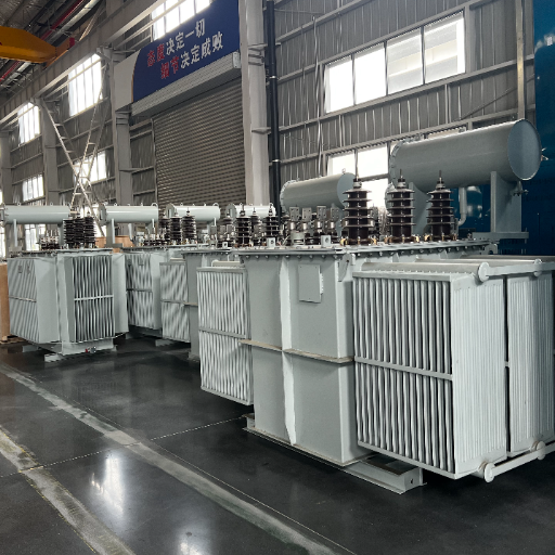
Operating without any mechanical moving components, a power transformer is not a type of rotating machinery. The primary-secondary transformation of energy takes place through electromagnetic induction where the fabricated steel core serves as a conduit for the whole mechanism. Their unique and simplistic design guarantees that well-crafted units work well for a period of three to even four decades with hardly a glitch.
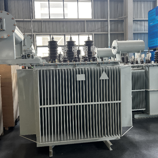
The key components of any power transformer include:
- Lamination Core: A high-energy-magnetic-flux-permeable path
- Windings Primary or Secondary: Two common types are usually copper or aluminum conductors-the transformer’s turn ratio determines the voltage transformation
- Isolation System: Oil-immersed paper, epoxy resin, or other dielectric materials that separate windings and prevent electrical shorts
- Efficiency Unit: Adjusts the effective number of winding turns to regulate output voltage
- Cooling System: The system dissipates heat, and various systems are used for electric losses including radiators, air channels, and bifurcated pumps, directly or indirectly
- Bushing: A bushing is just an insulated conductor used to bring the transformer leads through the top of the tank.
There are several primary distinctions between power and distribution transformers. Power transformers typically operate at voltages higher than 33kV, handle megavolt-amperes (MVA) of capacity, and designed to attain maximum efficiency at or near full load. Contrary to this, distribution transformers usually operate at voltages below 33kV and are characterized by a capacity of kilovolt-amperes (kVA) and partial-load efficiency attained over a 24-hour cycle.
How Power Transformers Work
Power transformers function according to Faraday’s Law which describes electromagnetic induction. The primary winding produces a magnetic field that changes continuously when alternating current passes through it. The process generates an expanding and collapsing magnetic flux which intersects the secondary winding to produce an electromotive force (EMF) in that winding.
The voltage transformation depends on the ratio of turns between the primary and secondary windings.
[
\frac{V_p}{V_s} = \frac{N_p}{N_s}
]
Where (V_p) and (V_s) stand for primary and secondary voltages, and (N_p) and (N_s) amount to the respective turn counts. When the secondary has more turns than the primary, the transformer steps voltage up; and when the secondary has lesser turns, the transformer does the exact opposite, i.e., it steps voltage down.
Since P = V × I, power roughly varies as the product of the current and the voltage. So increasing the voltage cuts the current required to transmit the same power. And because line losses are directly proportional to the square of the current (I^2R), thus multiplying the voltage moderately results in a very large decrease in energy loss. Scaling up of power from 11 kV to 400 kV results in reducing the transmission current by over 90 percent and therefore cuts resistive losses in approximately 400 times.
In an ideal transformer, input power equals output power. Real transformers are highly efficient, often reaching 98.5 percent or more at full load. The small energy loss that does occur appears as heat from two sources:
- Core losses (hysteresis and eddy currents in the steel laminations)
- Copper losses (resistive heating in the windings)
Managing these losses through proper cooling and high-quality materials is what separates a standard transformer from a premium industrial unit.
Engineering insight: Chen Wei, a project engineer at a Jiangsu manufacturing plant, achieved energy savings of 34 percent when he upgraded his facility’s supply voltage from 11 kV to 33 kV by installing a modern step-down power transformer. The upgrade paid for itself in under four years through reduced demand charges and lower resistive losses.
Types of Power Transformers
Engineers classify power transformers in several ways. Understanding these categories is essential because the right classification drives everything from cooling method selection to installation requirements and lifecycle cost.
By Voltage Function
Step-up transformers increase voltage from primary to secondary. They are used at power generation stations to raise generator output (typically 11 to 28 kV) to transmission levels (132 kV to 765 kV or higher) so electricity can travel long distances efficiently.
Step-down transformers decrease voltage. They appear at distribution substations and load centers, reducing high transmission voltages to medium or low voltages that industrial and commercial equipment can use safely. For a detailed comparison of both types, see our step-up transformer vs step-down transformer guide.
Isolation transformers provide a one-to-one turns ratio with galvanic isolation between primary and secondary. They protect sensitive equipment from electrical noise and ground loops.
Autotransformers use a single tapped winding rather than separate primary and secondary windings. They are more compact and efficient than conventional two-winding designs, but they do not provide electrical isolation. Common applications include voltage stabilizers and railway traction systems.
By Phase Configuration
Single-phase transformers have one primary and one secondary winding. They are simple, compact, and economical for small loads such as residential supplies, rural installations, and light commercial applications up to about 100 kVA.
Three-phase transformers contain three sets of windings on a shared core. They deliver constant power flow, produce smoother motor torque, and are significantly more efficient per kVA than three separate single-phase units. Any industrial facility with heavy motor loads will almost certainly use a three-phase transformer as its main supply unit. Read our full comparison of three-phase and single-phase transformers.
By Cooling and Insulation Method
Cooling class is one of the most important selection criteria because it directly determines how much power a transformer can handle safely and where it can be installed.
Oil-immersed transformers submerge the core and windings in mineral oil or synthetic ester fluid. The oil acts as both an electrical insulator and a coolant. Common cooling codes include:
- ONAN (Oil Natural / Air Natural): Base rating with no moving parts
- ONAF (Oil Natural / Air Forced): Adds radiator fans for 25 to 33 percent more capacity
- OFAF (Oil Forced / Air Forced): Uses oil pumps and fans for large power transformers
- ODAF (Oil Directed / Air Forced): Directs forced oil through winding ducts for maximum heat removal. Learn more about transformer cooling classes
Dry-type transformers use air or solid insulation (such as epoxy resin or vacuum pressure impregnation) instead of liquid. They are preferred for indoor installations where fire safety is critical, including hospitals, data centers, high-rise buildings, and subway stations. Compare dry type and oil filled transformers in detail.
By Core Construction
Core-type transformers have windings that surround a rectangular core. They are common for high-voltage applications because the winding arrangement makes insulation easier.
Shell-type transformers have a core that surrounds the windings. They offer better mechanical strength and lower leakage flux, making them suitable for low-voltage, high-current applications.
Power Transformer vs Distribution Transformer
The terms “power transformer” and “distribution transformer” describe where a unit sits in the grid as much as they describe its physical design. Here is how they compare. For the complete technical comparison, read our power transformer vs distribution transformer guide.
| Feature | Power Transformer | Distribution Transformer |
|---|---|---|
| Voltage level | Greater than 33 kV (up to 765 kV+) | Less than 33 kV (typically 11 kV to 415 V) |
| Power rating | 500 kVA to 500+ MVA | 3 kVA to 500 kVA (per IEEE 141) |
| Grid position | Generation and transmission substations | Near end users (pole-mounted, pad-mounted, or indoor) |
| Efficiency design | Maximum efficiency at or near full load | All-day efficiency at 50 to 70 percent load |
| Voltage regulation | Lower priority | Critical for stable consumer voltage |
| Maintenance | Frequent and rigorous | Lower frequency but often exposed to weather |
Power transformers form the backbone of long-distance transmission. Distribution transformers are the final link that delivers safe, usable voltage to homes, offices, and factories.
Power Transformer Specifications and Ratings
Selecting the right power transformer requires fluency in several key specifications. Getting any of these wrong can lead to overheating, premature failure, or costly over-engineering.
kVA and MVA Ratings
Transformers are rated in apparent power (kVA or MVA), not kilowatts. This is because a transformer must handle both real power (kW) and reactive power (kVAR). Its thermal limit depends on the total current flowing through the windings, which is determined by apparent power.
Standard three-phase distribution sizes include 15, 30, 45, 75, 150, 300, 500, 750, 1,000, 1,500, 2,000, and 2,500 kVA. Large power transformers for substations and transmission typically range from 5 MVA to 500+ MVA.
Engineers should always select the next standard size up from the calculated load requirement. Never size exactly to the calculated load. A common reserve margin is 1.3x for units below 1.6 MVA and 1.1x to 1.3x for larger units. For a step-by-step sizing methodology, see our transformer kVA/MVA selection guide.
Voltage Classes and BIL
The Basic Insulation Level (BIL) defines the maximum lightning impulse voltage a transformer can withstand without insulation failure. Typical BIL pairings include:
- 66 kV system: 325 kV BIL
- 132 kV system: 550 kV BIL
- 220 kV system: 1,050 kV BIL
- 400 kV system: 1,425 kV BIL
Bushing selection must match or exceed the transformer BIL. For outdoor installations in polluted environments, engineers must also verify that the bushing creepage distance meets local requirements.
Cooling Classes and Capacity
A single transformer can have multiple nameplate ratings depending on its cooling configuration. For example:
- 50.4 / 63 MVA, ONAN / ONAF: 50.4 MVA with natural cooling, 63 MVA with fans running
- 84 / 112 / 140 MVA, ONAN / ONAF / ONAF: Three stages of cooling with progressively higher capacity
Choosing the right cooling mode matters for both first cost and operating cost. ONAN has no moving parts and requires minimal maintenance. ONAF and OFAF add complexity but unlock significantly higher capacity for intermittent peak loads.
Derating for Environment
Under standard conditions, it is assumed that the ambient temperature is 40 degrees Celsius and the altitude is sea-level (1,000 meters or below). Derate the capacity by taking 1.5 percent of what rating it is per every single degree above 40 C. Altitudes above 1,000 meters usually mean that you have to derate by 3 percent at 2,000 meters and by 6 percent at 3,000 meters.
Applications of Power Transformers
Power transformers appear at nearly every stage of the electrical supply chain. Their applications span traditional utilities, heavy industry, and some of the fastest-growing sectors in modern infrastructure.
Power Generation and Transmission
The step-up transformers in a generation station carry the low voltage generated by turbines or generators to high voltage transmission levels. This step in the process is indispensable to making it economically feasible to move electricity hundreds of kilometers away or even thousands with acceptable losses.
Heavy Industry and Manufacturing
Large production facilities find step-down power transfonners very helpful in bringing down medium-voltage utility feeds to a level that can be used by large motors, drives, and process equipment. A typical facility may make use of, for example, 5MVA or 10MVA transformers that serve to step the voltage from 6.6 kV, stepping down from 33 kV, or to 480 V for use by motor control centers and variable frequency drive systems.
Renewable Energy
All power transformers are required by wind farms and solar plants in order to get connected to a grid. In a wind farm, turbine output voltage (often 690 V) is stepped up to 33 kV for export, but sometimes even to 110 kV. Solar inverters similarly require step-up transformers to maintain this step-up-to-voltage rating. Globally, the rise of renewables sets out a special growth driver for a 6-7% annual growth of the power transformer market through the 2030s.
Data Centers and Critical Infrastructure
Data centers demand reliable, clean power with minimal fire risk. Many facilities use dry-type transformers installed indoors near the load to step medium-voltage feeds down to 480 V or 400 V for server racks. The absence of flammable liquid makes dry-type units the preferred choice for buildings with strict fire codes.
Railways and Traction Power
Electric railways use dedicated power transformers to supply traction substations. These units often feature robust mechanical designs and specialized vector groups to handle the severe loading cycles of train acceleration and braking.
Transformer Components Explained

Understanding the major components of a power transformer helps engineers specify units correctly and communicate effectively with manufacturers.
Core and Windings
The core is constructed of thin insulated silicon-steel laminations designed to minimize eddy-current losses. Conductors are typically copper but aluminum may be used in some instances to reduce weight as well as cost. The choice of the conductor material, the winding methods, and the insulation system all help set the resistance against short-circuit forces and thermal failure.
On-Load Tap Changer (OLTC)
Under on-line tap changer operation, the turns ratio of the transformer is regulated while it remains energized and under load, facilitating the real-time maintenance of voltage for offsetting fluctuations in the grid and changing external demand. In addition, it is common practice to have OLTCs run on the HV windings. It serves to carry lower current and allows you to achieve finer operating steps.
Modern vacuum types of the on-line tap changer are capable of more than 5,00,000 trouble-free operations. The typical regulation range being plus or minus 10 percent of rated voltage, with 0.625 percent, 1.25 percent, or 1.5 percent step sizes per tap.
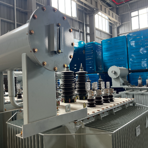
Bushings
The core hearth bricks cemented to the tank wall serve as bushing insulation for high-voltage conductors. Standard bushing types are the capacitor graded (Omiss, Riss, or Ris) for voltages exceeding 23 kV. The repercussions of a bushing failure are more severe; American data proves that bushings are culpable for up to 30 percent of failure-caused transformer fires.
Cooling System and Conservator
In oil filled transformers, the conservator is a small tank mounted on the top of the main tank for accommodating oil with expansion and contraction due to variations in temperature. The breather of silica gel will keep moisture out of the oil. The cooling system may consist of radiators, fans, oil pumps, and temperature indicators that help to maintain winding temperatures within design limits.
Protection Relays
A complete protection scheme combines electrical and non-electrical relays, often monitored through instrument transformers (CT and PT):
- Differential protection: Detects internal faults by comparing input and output currents
- Buchholz relay: Detects gas accumulation and sudden oil flow caused by internal arcing
- Thermal protection: Monitors oil and winding temperature, typically alarming at 85 C and tripping at 95 C
- Pressure relief device: Opens rapidly if internal pressure spikes, preventing tank rupture
Transformer Maintenance and Reliability
Power transformers are reliable; however, they require some maintenance. The Transformer Reliability Survey of CIGRÉ found that substation transformers typically had 0.53% per year failure rates, with generator step-up transformers,100.95% per year. In total, roughly 45 to 48% of major failures are ascribable to windings, while on-load tap changer accounts for 26 to 41%.
The good news is that most failures are preventable with disciplined monitoring and maintenance.
Oil Testing and Analysis
Dissolved Gas Analysis (DGA) is the most dominant predictive tool in the case of an oil-immersed unit. It is capable of detect-ing fault gases: hydrogen, methane, ethylene, acetylene and carbon monoxide, which get generated under overheating or arcing of oil and insulation. Acetylene is indeed a big indicator for internal arcing.
Other critical oil tests include:
- Dielectric breakdown voltage (BDV): Measures the oil’s ability to resist electrical stress. New oil should exceed 60 kV; in-service oil should remain above 30 kV.
- Moisture content: Even trace water reduces insulation strength dramatically. Keep moisture below 30 ppm for in-service oil in extra-high-voltage units.
- Acidity (TAN): Indicates oxidation and oil degradation. Values above 0.4 mg KOH/g typically require oil reclamation or replacement. See the complete transformer oil testing and maintenance guide
Thermal Monitoring
Infrared thermography can reveal hot spots in terminals, connections, and cooling systems before they cause failure. Online temperature monitors and fiber-optic winding hot-spot sensors allow continuous tracking of the most temperature-sensitive parts of the unit.
Common Failure Prevention
Overheating is responsible for up to 70 percent of premature transformer failures. For every 10 C rise above the rated temperature limit, insulation life is approximately halved. Key preventive measures include:
- Keeping sustained load below 80 percent of rated capacity where possible
- Ensuring cooling fans and pumps operate correctly
- Cleaning dust from radiators and air intakes quarterly
- Verifying that seals and breathers keep moisture out of the oil
- Using K-rated transformers in environments with high harmonic loads from low-voltage VFD systems
For a comprehensive breakdown of failure modes and preventive strategies, read our transformer failure causes and prevention guide.
Field example: Li Hao, the maintenance supervisor at a water treatment plant in Shanghai, observed his water transformer running 12 C above normal in the summer during peak loads. Due to the presence of blocked cooling fins and a failed radiator fan, his infrared scan was successful. The temperature gauge of the transformer showed a drop of 15 C, following the cleaning of the fins and the installation of the radiator fan. Li Hao estimated that maintenance measures would have lengthened the life of the unit by between 8 and 10 years.
How to Choose the Right Power Transformer
Selecting a power transformer is a multi-factor engineering decision. The following framework will help you navigate it systematically.
Step 1: Calculate the Load
Determine the total apparent power (kVA) of all connected loads. For three-phase systems:
[
kVA = \frac{V \times I \times 1.732}{1,000}
]
If you know the real power in kW, divide by the load power factor to get kVA.
Step 2: Apply a Reserve Margin
Add spare capacity for future growth, motor starting inrush, and load diversification. A margin of 1.3x is common for units below 1.6 MVA. For larger transformers, 1.1x to 1.3x is typical.
Step 3: Define the Environment
Ask these questions:
- Will the transformer be installed indoors or outdoors?
- Are there fire safety restrictions that favor dry-type over oil-immersed?
- What is the maximum ambient temperature and altitude?
- Is the site exposed to dust, salt air, or corrosive chemicals?
Step 4: Select Cooling Class
Match the cooling method to the load profile. If the transformer will run continuously at high load, specify adequate cooling (ONAF or OFAF) from the very beginning. If peak loads are intermittent, a dual-rated unit with a cooling mode of ONAN/ONAF is the best choice in terms of both initial cost and ability to perform.
Step 5: Specify Standards
Identify which standards apply to your project:
- IEC 60076: Global standard for power transformer design, testing, and performance
- IEEE C57.12.00 / C57.12.90: Dominant in the Americas; includes general requirements and test codes
- IEEE C57.120: Provides the loss evaluation framework used by North American utilities
For export projects, verify that the transformer meets the destination country’s efficiency and safety regulations. IEC-based MEPS (minimum energy performance standards) are increasingly common in Asia-Pacific and Middle Eastern markets.
Step 6: Verify Integration Requirements
Consideration shall be given to the manner in which the transformer will interface with downstream equipment. If your plant has many motor drives, LED lights, or any other non-linear load, stay conscious with regard to the issue of harmonic heating. Specifying a K-rated transformer in such a case will be necessary. K-13 is typical for data centers and mixed industrial loads, while K-20 may be required for severe high non-linear environments.
Frequently Asked Questions
What is a power transformer?
A power transformer is a static electrical device that transfers energy between circuits through electromagnetic induction, typically stepping voltage up for transmission or down for distribution. It operates without moving parts and is rated in kVA or MVA.
How does a power transformer work?
We are concerned with the Faraday’s law of induction. The changing magnetic field in the core produced by alternating current in its primary calls for the development of a voltage in the secondary winding. This voltage is dependent on the certain turns-ratio between the primary and secondary windings and is either stepped up or stepped down.
What is the difference between a power transformer and a distribution transformer?
Power transformers are the high-voltage (above 33 kV), large capacity (in the MVA range) machines located in the transmission network. By contrast, the distribution transformers are the lower voltage (below 33 kV), lower-capacity (in kVA range), and proximity to users. Power transformers are released by full-load efficiency as opposed to distribution transformers with part-load efficiency over the entire 24-hour period.
How efficient is a power transformer?
Large modern power transformers routinely achieve efficiencies of 98.5 percent or higher at full load. Losses are limited to core losses (hysteresis and eddy currents) and copper losses (resistive heating in the windings).
What causes power transformers to fail?
The prime causes are insulation failures, overheating, moisture penetration, and electrical faults, which include short circuits and lightning strikes. Usually 45- to 48-percent of significant failures are attributed to the windings, and the on-load tap changers account for 26- to 41-percent while most of the failures can be easily avoided by proper sizing, cooling, and doing regular oil testing.
How long does a power transformer last?
Design life is typically 25 to 30 years. However, well-maintained units often exceed 40 years of service. Regular dissolved gas analysis, thermal monitoring, and cooling system maintenance are the key factors that extend transformer life.
Can a power transformer be used indoors?
True, but cooling and insulation types should match placement. It is recommended that dry‐type transformers be used for indoor application because they do not contain flammable liquid. Oil‐filled transformers can only be installed indoors if kept within specially designed fireproof vaults with arrangements for oil containment and fire fighting.
Conclusion
Power transformers are one of the most critical and long-lived assets in an electrical infrastructure. Specifying the correct unit is not just a matter of finding the right voltage and catalog number; it also involves clear understanding of electromagnetic principles, cooling classes, environmental constraints, and lifecycle economics.
The key takeaways are straightforward:
- Size in kVA or MVA, not kW, and always include a future-growth margin
- Match the cooling class to your actual load profile and installation environment
- Choose dry-type for indoor fire-sensitive applications and oil-immersed for maximum efficiency and capacity outdoors
- Specify the right standards (IEC or IEEE) for your market and project
- Invest in preventive maintenance, especially oil testing and thermal monitoring, to maximize service life
At Shandong Electric, we design and provide an industrial electrical solution that harmonizes with modern motor control and automation systems. From 3-phase VFD drives up to power distribution transformers, our engineering team works in tandem with the client right from the selection to commissioning to ensure decades of reliable operation of the system.