Transformer Failure Causes and Prevention: A Data-Driven Guide for Industrial Facilities
The leading transformer failure causes are winding insulation breakdown (29%), transient overvoltage (16%), and bushing failure (14%), with most incidents preventable through predictive maintenance and thermal monitoring. A disciplined prevention program costs a fraction of the $3 million average failure price tag.
In March 2024, a paper mill in Michigan lost a 2,500 kVA distribution transformer during peak production. The winding insulation had degraded for three years unnoticed. Replacement cost 185,000.Lostproductioncostanother185,000.Lostproductioncostanother420,000. The root cause was thermal overload from harmonic distortion, a problem that dissolved gas analysis would have caught 18 months earlier.
The expensive nature of transformer failures is well understood amongst the maintenance teams. What remains sought after is a simplified summary with emphasis on identifying the critical failure modes encountered, when early warning signs present themselves, and what works the best toward prevention.
This guide is abounding with IEEE-inspired statistics behind the causes and prevention of transformer failures, the top seven root causes, most incidents, early warning signs, and practical measures for prevention. You will learn how to apply a proper and effective maintenance stack in order to net issues before they escalate to outages.
Key Takeaways
- Winding insulation breakdown (29%), transient overvoltage (16%), and bushing failure (14%) are the top three identifiable causes per IEEE data.
- Predictive maintenance reduces annual transformer failures by 62% and cuts maintenance costs by 52%.
- For every 10 degrees Celsius above rated temperature, insulation life is cut in half.
- A disciplined transformer failure causes and prevention stack combining DGA, thermal imaging, and load monitoring catches most failures months in advance.
- Factory build quality and proper K-factor specification directly affect long-term failure risk.
For a more in-depth understanding of power transformers, (please refer to our complete guide to power transformers.)
What the Data Says: Transformer Failure Causes and Prevention Statistics
Understanding transformer failure causes and prevention starts with the data, and the numbers tell a clear story. Utilities and industrial operators have been collecting failure statistics for decades, and the patterns are clear.
Failure-Initiating Causes by Percentage
The IEEE Gold Book (IEEE Std 493, Appendix F) documents failure-initiating causes based on large-scale utility surveys. The distribution is consistent across North American and international datasets.
| Failure-Initiating Cause | Percentage | Typical Repair Cost |
|---|---|---|
| Winding insulation breakdown | 29% | 150,000−150,000−500,000 |
| Transient overvoltage disturbance | 16% | 80,000−80,000−300,000 |
| Insulation bushing breakdown | 14% | 40,000−40,000−120,000 |
| Mechanical breaking or loosening | 7% | 30,000−30,000−100,000 |
| Loose connection or termination | 7% | 10,000−10,000−50,000 |
| Other insulation breakdown | 6% | 50,000−50,000−200,000 |
| Protective relay malfunction | 5% | 5,000−5,000−25,000 |
| Improper operating procedure | 4% | 20,000−20,000−80,000 |
| Overheating | 3% | 100,000−100,000−400,000 |
| Other mechanical damage | 3% | 25,000−25,000−100,000 |
| External damage (digging, vehicles) | 3% | 50,000−50,000−250,000 |
| Animal or tool shorting | 1% | 15,000−15,000−60,000 |
Combined, winding, tap-changer, and bushing failures represent more than 85% of all transformer failures. Winding failures alone constitute the majority. This concentration means prevention efforts focused on insulation health, thermal management, and surge protection will address the highest-risk areas.
Failure Rates and Economic Impact
Transformer failure rates generally range from 0.5% to 2.0% per transformer-service-year according to CIGRE and IEEE references. The probability of a major failure requiring replacement or major repair is roughly 1% per service year.
The economic impact is substantial. An IMIA study of 94 transformer failures between 1997 and 2001 documented total losses of 286.6million∗∗,averagingroughly∗∗286.6million∗∗,averagingroughly∗∗3 million per incident. Property damage accounted for 163.2millionandbusinessinterruptionfor163.2millionandbusinessinterruptionfor123.4 million.
A more revealing comparison comes from 10 U.S. utilities tracked over multiple years:
| Metric | Reactive Maintenance | Predictive Maintenance |
|---|---|---|
| Annual failures | 120 | 45 |
| Total annual cost | $30 million | $14.4 million |
| Average repair cost | $250,000 | $160,000 |
| Annual downtime hours | 9,000 | 3,200 |
That’s a 62% reduction in failures and $15.6 million in annual savings. The data makes the business case for prevention unmistakable.
If you operate oil immersed transformer designs in demanding environments, the financial case for predictive maintenance is even stronger. Oil-filled units have more failure modes to monitor but also more diagnostic tools available.
The Seven Root Causes of Transformer Failure
Effective transformer failure causes and prevention requires understanding root categories. These seven failure modes help maintenance teams prioritize prevention efforts and allocate budgets where they’ll have the most impact.
Winding Insulation Breakdown and Thermal Stress
Transformer winding failure is the single largest category. Windings are the heart of the transformer, and when insulation between turns or layers degrades, the result is a short circuit, open circuit, or ground fault.
Thermal stress is the primary accelerator. For every 10 degrees Celsius rise above the rated temperature, insulation life is approximately halved according to the Arrhenius equation. Operating consistently above 80% of rated load pushes many units into accelerated aging. Harmonic distortion from variable frequency drives, LED lighting, and switching power supplies adds eddy-current heating that standard thermal models don’t account for.
Prevention: Dissolved gas analysis annually, infrared thermography every six months, and K-factor transformer specification for harmonic-rich loads to reduce transformer winding failure risk.
Transient Overvoltage and Lightning Strikes
High-impulse voltages caused by switching operations, capacitor bank switching, or direct lightning are capable of puncturing insulation or distorting windings. A transformer is left unprotected because the surge protection system on the transformer line is either not present or is inadequate.
Lightning is responsible for somewhere between 11 and 18% of installations compromised by outside conditions. The surges created by the transient clearing of faults from their vicinity result in overvoltages several times the normal operating voltage.
Prevention: Properly rated surge arresters at the transformer terminals, verified grounding systems, and regular inspection of surge protection devices.
Bushing and Terminal Failures
Transformer insulation breakdown frequently starts at the bushings. These components bridge the gap between the internal windings and external conductors. They are exposed to weather, contamination, and mechanical stress from conductor movement.
Cracked porcelain, oil leaks at gasket interfaces, and tracking across contaminated surfaces are common failure paths. A bushing failure often cascades into internal damage when the fault current travels through the tank.
Prevention: Annual visual inspection, cleaning of contamination, torque verification of terminals, and replacement of bushings showing signs of tracking or oil seepage.
Moisture Ingress and Oil Contamination
On the oil-filled system, it is moisture that hastens deterioration. Water can exist in several forms: free water, emulsified water, water that is dissolved frequently, and water that is bound in paper insulation. The interaction of moisture and cellulose insulation directly contributes to the degradation of the latter, resulting in the formation of solid acids and sludge that impair the cooling efficiency and lead to an escalating cycle of accelerated aging.
For dry type transformer units, moisture in windings, chemical contamination, and salt spray are common culprits. Once paper insulation moisture exceeds 2% by weight, the risk of transformer insulation breakdown rises sharply.
Prevention: Maintain silica gel breathers, monitor oil moisture content with Karl Fischer testing, and consider oil filtration or reclamation when moisture exceeds 30 ppm to prevent transformer insulation breakdown.
Mechanical Damage and Through-Fault Stress
Through-faults (short circuits on the load side of the transformer) generate massive electromagnetic forces. These forces can loosen winding clamps, deform coils, and shift core laminations. The mechanical damage is often invisible until a subsequent thermal or electrical stress triggers total failure.
Shipping and installation damage also falls in this category. A transformer dropped or tilted beyond specifications during delivery may have shifted internal clearances that won’t show up until energized.
Prevention: Frequency response analysis (FRA) after major through-faults, proper rigging and leveling during installation, and verification of clamping pressure during overhaul.
Cooling System Malfunctions
Blocked coolant pathways, failed fans or pumps, sludge buildup, or obstructed air intakes restrict heat dissipation. In extreme cases, this leads to thermal runaway where rising temperature increases losses, which further increases temperature.
A maintenance team in Ohio caught a cooling issue before it became catastrophic. During a quarterly infrared scan, they found a 25-degree Celsius hot spot on the top oil line of a 5 MVA unit. Investigation revealed a failed circulation pump. The repair cost $3,200. Without detection, the transformer would have failed within weeks due to thermal degradation of the winding insulation.
Prevention: Clean cooling fins and radiators quarterly, verify fan and pump operation, and monitor oil temperature trends for gradual increases.
Overloading and Harmonic Distortion
Transformer overload prevention is critical because sustained overloading is one of the most common operational causes of failure. Standard transformers are not designed for continuous operation above nameplate rating.
Harmonic currents from nonlinear loads cause additional heating beyond what a standard true-RMS ammeter measures. A load drawing 100 amps fundamental current with 30% total harmonic distortion may produce the heating effect of 115 to 120 amps. Standard thermal models miss this entirely.
Prevention: Continuous load monitoring with true-RMS meters, load balancing across phases, and specification of K-factor rated transformers (K-13 or K-20) in environments with high harmonic content support effective transformer overload prevention.
Early Warning Signs Your Transformer Is Failing
Transformer failure causes and prevention both depend on early detection. Most failures announce themselves through audible, visual, thermal, and electrical indicators that a trained observer can detect weeks or months in advance.
Audible and Visual Indicators
- Unusual humming, buzzing, or vibration beyond normal 60 Hz hum
- Oil leaks at gaskets, bushings, or welds
- Discolored or cracked bushings
- Bulging tank walls or pressure relief device activation
- Burning odor near the transformer
Thermal and Electrical Indicators
- Excessive temperature rise above historical baseline
- Hot spots detected during infrared scanning
- Unexplained increase in no-load losses
- Erratic secondary voltage or voltage imbalance
- Frequent operation of protective relays
Oil Quality Red Flags
For liquid-filled units, oil condition is a direct indicator of internal health:
- Darkening color or visible sludge
- Moisture content above 30 ppm
- Dielectric breakdown voltage below 30 kV
- Rising acidity above 0.2 mg KOH/g
- Elevated dissolved gas levels, especially acetylene
If you observe multiple warning signs simultaneously, de-energize the unit and perform diagnostic testing before returning it to service.
Transformer Maintenance Best Practices for Prevention
Transformer maintenance best practices combine multiple diagnostic techniques into a layered prevention stack. No single test catches every failure mode, but together they provide comprehensive coverage.
Dissolved Gas Analysis and Oil Testing
DGA is the industry standard for early fault detection. It measures hydrogen, methane, ethane, ethylene, and acetylene dissolved in the oil. Each gas indicates a specific type of fault:
| Gas | Typical Source | Action Threshold |
|---|---|---|
| Hydrogen | Partial discharge | Trend upward warrants investigation |
| Methane | Low-temperature overheating | Monitor trend over time |
| Ethylene | High-temperature overheating | > 50 ppm indicates serious concern |
| Acetylene | Arcing / high-energy discharge | Any detectable level requires immediate action |
| Carbon monoxide | Paper insulation degradation | Correlates with solid insulation aging |
Transformer maintenance best practices include scheduling DGA annually for critical assets and every two years for standard distribution units. Combine DGA with dielectric breakdown voltage, moisture content, and acidity testing for a complete oil health picture.
Infrared Thermography and Hot Spot Detection
Infrared scanning detects hot spots caused by loose connections, overloaded bushings, blocked cooling, and internal winding problems. Annual thermography is standard practice for critical assets. Scan terminations, bushings, tank surfaces, and cooling systems.
Effective transformer thermal protection also relies on temperature differentials. A difference of more than 10 degrees Celsius between similar components indicates a problem requiring investigation.
Load Monitoring and Thermal Management
Transformer thermal protection starts with knowing your actual load profile. Many facilities assume they are within rating because the peak load is below nameplate. They miss the fact that sustained operation at 85% to 95% of rating, combined with harmonics and high ambient temperatures, produces the same thermal aging as intermittent overloads.
Transformer overload prevention starts with continuous load monitoring using true-RMS meters. Redistribute loads to avoid sustained operation above 80% capacity as part of your transformer overload prevention program. Specify transformer efficiency ratings that account for harmonic content in your facility.
Surge Protection and Grounding Verification
Inspect surge arresters annually for physical damage, contamination, and proper connection. Test ground resistance every two years. Many utilities require 5 ohms or less for distribution transformer installations.
After any nearby lightning strike or switching event, inspect arresters for signs of operation and verify the transformer with insulation resistance testing.
Cooling System and Bushing Inspection
Clean cooling surfaces quarterly. Verify fan, pump, and thermostat operation. Inspect bushings for cracks, contamination, and oil leaks. Torque terminal connections to manufacturer specifications annually. These transformer maintenance best practices form the foundation of any reliable prevention program.
Send your voltage, kVA, and load profile to Shandong Electric Co., Ltd. for a maintenance planning review. Our engineering team can recommend the optimal testing schedule and diagnostic stack for your specific asset class.
When to Repair, Refurbish, or Replace
Transformer failure causes and prevention programs eventually face a replacement decision. At some point, every transformer reaches a condition where continued operation is riskier than replacement. The decision depends on age, condition, and the cost of failure versus the cost of replacement.
Age-Based Decision Thresholds
| Age Range | Typical Condition | Recommended Action |
|---|---|---|
| 0 – 10 years | Generally reliable | Standard predictive maintenance |
| 10 – 20 years | Early aging signs | Increase testing frequency, plan for refurbishment |
| 20 – 30 years | Significant insulation aging | Detailed condition assessment, budget for replacement |
| 30+ years | High failure risk | Replace unless exceptional condition documented |
The average failed transformer is approximately 18 years old. However, units in harsh environments, heavily loaded conditions, or with poor maintenance history may fail much earlier.
Condition-Based Decision Framework
Use this matrix to guide repair versus replace decisions:
| Condition Indicator | Repair | Refurbish | Replace |
|---|---|---|---|
| DGA trend | Stable or slowly improving | Rising thermal gases, no acetylene | Acetylene present or rapidly rising |
| Oil quality | BDV > 40 kV, acidity < 0.2 | BDV 30-40 kV, acidity 0.2-0.4 | BDV < 30 kV, acidity > 0.4 |
| Insulation resistance | > 90% of factory value | 70-90% of factory value | < 70% of factory value |
| Physical condition | No leaks, no deformation | Minor leaks, manageable | Major leaks, tank deformation |
| Load growth headroom | > 25% spare capacity | 10-25% spare capacity | < 10% spare capacity |
The Hidden Cost of Waiting Too Long
A utility in the Southwest delayed replacement of a 30-year-old substation transformer because the capital budget was tight. When the unit finally failed during summer peak load, emergency replacement cost 40% more than planned procurement. Temporary mobile substation rental added 12,000perdayforthreeweeks.Thetotalunplannedcostexceeded12,000perdayforthreeweeks.Thetotalunplannedcostexceeded800,000.
Planned replacement almost always costs less than emergency failure response. Include transformer replacement planning in your five-year capital budget cycle.
For a deeper technical breakdown of industrial transformer oil testing and maintenance practices, see our Transformer Oil Testing and Maintenance: A Practical Guide for Industrial Facilities.
How Factory Quality Reduces Long-Term Failure Risk
Most transformer reliability-affecting decisions are made prior to a shipment from the factory. Factory build quality, core design, and initial oil condition make the baseline for how long to go on serving or heading for failure.
Core Design and Thermal Performance
Under different load levels, fragments in the low-loss core can discharge considerably less heat. The lower operating temperatures largely affect the aging of insulation and extend the life of transformers. For every watt of no-load loss eliminated, the transformer runs cooler and the oil degrades more slowly.
Winding Quality and Impulse Testing
Factory impulse testing verifies that windings can withstand lightning and switching surges. Units from manufacturers with rigorous testing programs have lower field failure rates from transient overvoltage events. Request impulse test reports with your factory documentation.
Oil Quality at Delivery
While some miles away from ASTM D3487 specifications, new oil will still display a dielectric strength of over 60 kV, moisture content rarely exceeding 15 ppm, and acidity well below 0.03 mg KOH/g. This is because preservation allows oil to stay long without depreciation. Ask certified oil test reports and use them as the maintenance baseline.
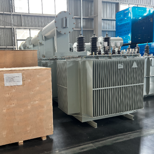
Export Packaging and Handling
Vibrations, humidity, and shipping stress from foreign shipments are among many tormentors to the transformer. Proper export crating, desiccant protection, and shock indicators are expedient for controlling physical damages during transportation. Check for shipping damages when taking a delivery.
If you are sourcing a pad mounted transformer or oil immersed unit for a utility or industrial project, request factory test reports, impulse test data, and oil quality certificates with your quotation. Complete documentation reduces commissioning risk and establishes your maintenance baseline.
Frequently Asked Questions
What is the most common reason a transformer fails?
Winding insulation breakdown is the most common identifiable cause, contributing to 29% of failures, according to IEEE. This is caused by the thermal stress from overloading, poor cooling or harmonic distortion, all of which get worse until the insulation eventually fails to hold against electrical stress.
Can a transformer fail without warning?
Most equipment failures give a lot of warning months before they happen. Any strange noise, rising temperature, change of color of oils or increase in dissolved gases all give off signs of an incipient problem. The few sudden malfunctions seem to be brought about by direct lightning strokes or extreme through-faults.
What causes insulation failure in transformers?
The insulation failure results from thermal aging, moisture, oxidation byproducts, and electrical overcurrent. For instance, for every 10 degrees over rated temperature, the life of insulation is halved. On the other hand, moisture above 30 ppm in oil or 2% in paper greatly accelerates the process.
Can overloading cause a transformer to fail?
Yes. Sustained overloading is one of the leading operational causes of failure. Standard transformers are not designed for continuous operation above nameplate rating. Harmonic currents from nonlinear loads produce additional heating beyond what standard ammeters measure.
How often should transformer oil be tested?
Test oil annually for critical assets and every two years for standard distribution transformers. Increase frequency after fault events, overload periods, or when previous tests show marginal results. At a minimum, test dielectric breakdown voltage, moisture content, and acidity.
Is replacement always necessary after an explosion?
Not always, but usually. Minor tank damage may be repairable if the core and windings are undamaged. However, most explosions result from internal faults that damage windings or insulation. A thorough internal inspection and diagnostic testing are required before any repair decision.
Conclusion
Effective transformer failure causes and prevention comes down to five principles:
- Monitor winding insulation health with DGA, infrared scanning, and load profiling
- Manage thermal stress through cooling system maintenance, load balancing, and K-factor specification
- Protect against transient overvoltage with properly rated surge arresters and verified grounding
- Establish factory oil quality baselines and trend test results over time
- Plan replacement on a condition and age basis, not a failure basis
Failure in transformers is costly, but it is not fixed; data shows that 85% of failures are grouped into three categories: winding, bushing, and tap changer. Therefore, a clean prevention stack directed at these areas with DGA (Dissolved Gas Analysis), thermal imaging, and load monitoring results in most issues being detected months before an outage.
Send your voltage, kVA, and site conditions to Shandong Electric Co., Ltd., a leading transformer manufacturer, for a factory-direct quotation with low-loss designs, comprehensive testing documentation, and engineering support for long-term reliability planning.
For a deeper technical breakdown of instrument transformer CT and PT selection criteria and standards, see our Instrument Transformer CT PT Guide: Selection, Standards, and Procurement.