Pad Mounted Transformer Installation Guide: A Step-by-Step Guide for Contractors and EPCs
The installation of a pad mounted transformer demands multiple requirements which include a concrete pad that needs to be level and specific clearance measurements and effective grounding methods and correct cable connections and testing of equipment before utility approval. Most installation failures trace back to decisions made before the unit ever reaches the site.
A solar EPC team from Texas installed a 1500 kVA unit last autumn when they positioned the equipment onto a pad which appeared level to their physical observation. The system needed inspection after three weeks because it produced abnormal sounds while its oil temperature continued to rise. The transformer was tilted 3.5 degrees. The internal components had shifted above the oil line which created a fire hazard because it decreased their insulation protection. The crew had to de-energize the unit because they needed to re-rig and re-level it which resulted in an $8,000 expense for both labor and equipment downtime.
The majority of contractors recognize that installation errors lead to significant financial losses. The process becomes more efficient when organizations establish correct specifications before beginning their procurement procedures.
The guide provides complete information for each step which starts from site preparation and ends at commissioning. The user will acquire knowledge about concrete pad specifications and clearance requirements and grounding procedures and common errors and the tests which need to be conducted before energization.
Key Takeaways
- A level concrete pad extending at least 6 inches beyond the transformer base is non-negotiable; tilt must not exceed 2 degrees.
- Maintain 10 feet of clearance in front of the unit and 3 feet on sides and rear for safe operation and maintenance access.
- Ground the tank, neutral, and doors to a dedicated ground grid using #2 AWG copper minimum before making any electrical connections.
- Pre-energization testing must include insulation resistance, turns ratio, and oil quality checks for liquid-filled units.
- Coordinate utility inspection and documentation handoff early to avoid delays in final energization approval.
For a more in-depth understanding of power transformers, (please refer to our complete guide to power transformers.)
Before You Order: Specifications That Affect Installation
The fastest way to simplify installation is to confirm specifications before the transformer ships. Errors in voltage, tap settings, or vector group alignment create field problems that are expensive to fix.
Verify Nameplate Data Early
Review the single-line diagram against the proposed nameplate data before placing the order. Confirm primary voltage, secondary voltage, kVA rating, frequency, impedance, and vector group. A mismatch between the ordered vector group and the existing switchgear configuration can require a full rewind or replacement.
Request certified factory test reports per IEEE C57.12.90. These reports document ratio, polarity, winding resistance, no-load loss, load loss, and applied potential tests. Having them on hand before arrival accelerates commissioning and satisfies most utility inspection requirements.
Voltage, Taps, and Vector Group Alignment
Verify that the transformer tap changer settings match the actual system voltage at the installation site. Primary voltage can vary by several percent depending on distance from the substation. Selecting the wrong tap forces field adjustment under energized conditions.
Confirm whether the project requires loop-feed or radial-feed construction. Loop-feed units have primary bushings on both ends for network redundancy. Radial-feed units bring power in from one side only. Mixing these configurations creates cable routing problems in the field. If your project changes voltage levels between generation and distribution, review step up transformer vs step down transformer requirements before locking in the ratio.
Factory Documentation and Export Readiness
For international projects, confirm that documentation matches local utility language and standard requirements. IEC-oriented utilities need test certificates referencing IEC 60076, while North American projects typically require IEEE and NEMA compliance. Incomplete documentation is a common cause of customs delays and inspection rejections.
If your project needs a custom pad mounted transformer with specific voltage ratios or enclosure features, share those requirements during the quotation phase. Retrofitting a standard unit in the field costs significantly more than factory customization.
Send your voltage, kVA, and site conditions to our engineering team for a specification review before you order.
Site Preparation and Foundation Requirements
Site work should be complete before the transformer arrives. Pouring concrete, trenching conduit, and installing grounding grids all take time. Doing this work in parallel with manufacturing keeps the overall project on schedule.
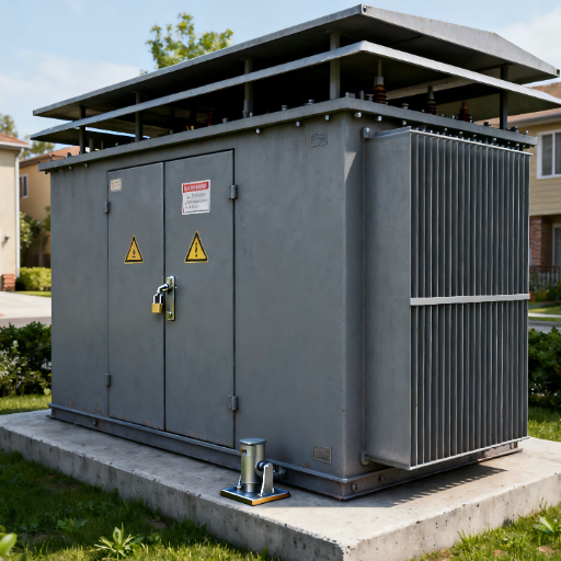
Pad Mount Transformer Clearances and Site Selection
Select a location with adequate working space and proper drainage. The area must be accessible for crane delivery and future maintenance vehicles. Avoid low-lying areas where water pools or flood risk exists. If your project requires indoor voltage conversion instead, review our dry type transformer guide for safety-critical environments.
Minimum clearances vary by utility and local code, but standard practice follows these guidelines:
| Location | Minimum Clearance |
|---|---|
| Front (access side) | 10 feet |
| Sides and rear | 3 feet |
| Door swing radius | 12 inches beyond arc |
| Adjacent walls or equipment | 6 inches minimum |
| Overhead obstructions | Adequate for crane rigging |
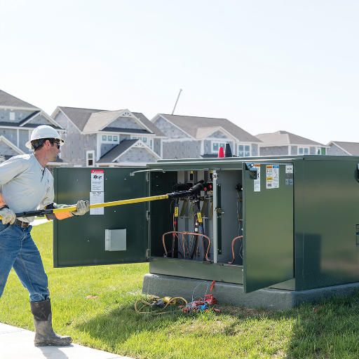
Maintain 10 feet in front for hot-stick operation. Do not place fixed bollards or barriers within the required front clearance zone. Where vehicle traffic is present, install 4-inch concrete-filled steel bollards at pad corners, set 40 inches below grade and 60 inches above grade.
Concrete Pad Specifications
Pour a reinforced concrete housekeeping pad sized to support the full unit weight plus dynamic installation loads. Standard specifications include:
- Dimensions: Minimum 6 inches wider and longer than the transformer base on all sides
- Thickness: 6 to 8 inches minimum with #4 rebar at 12 inches on center
- Strength: 3,000 psi compressive strength minimum
- Elevation: 2 to 4 inches above final grade to prevent water pooling
- Level: Perfectly level with no slope; maximum allowable tilt is 2 degrees
The pad must be fully cured before loading. Seven days is a practical minimum for most concrete mixes, though 28-day full cure is ideal for load-bearing confidence. Some utility specifications require a structural engineer’s stamp on the pad design.
Conduit Stub-Ups and Drainage
Install primary and secondary conduits before pouring the pad. Stub them up directly beneath their respective cable compartments. Use PVC schedule 40 or rigid galvanized conduit sized for the cable outer diameter plus a pull factor.
Ensure positive drainage around the pad perimeter. A 4-inch drain to daylight is commonly specified for utility projects. Where oil containment is required, integrate a containment pit or oil-separator system into the foundation design.
Grounding Grid Installation
Install the site grounding grid before the pad pour. Typical utility practice uses a #4/0 bare copper ground loop buried 30 inches below grade and 12 inches from the pad perimeter, bonded to two or more ground rods. Testing the grid resistance before the transformer arrives avoids costly rework.
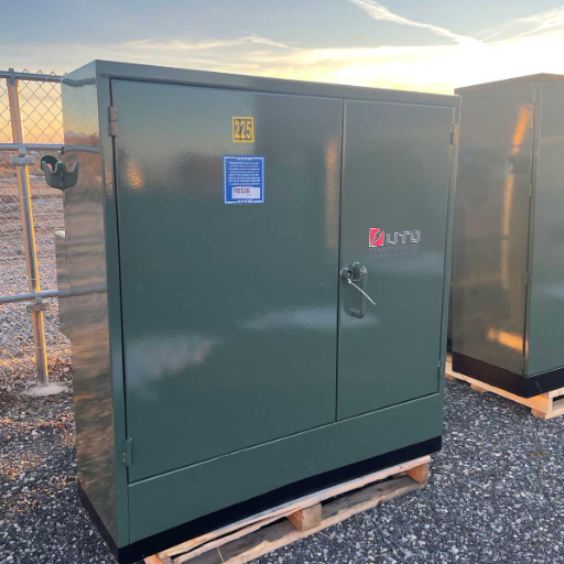
Receiving, Inspection, and Placement
The day of delivery sets the tone for the entire installation. A structured receiving process catches shipping damage and verifies that the correct unit arrived.
Unloading and Rigging Safety
Use a crane with adequate capacity for the unit weight plus rigging. Most three-phase pad mounted transformers weigh between 3,000 and 8,000 pounds depending on kVA rating. Attach lifting lines only to designated lifting lugs. Never pull on sheet metal moldings, radiators, or cabinet edges.
Verify that the crane operator understands the center of gravity. Pad mounted transformers are front-heavy due to the cable compartments. Use tag lines to control rotation during the lift.
Inspection Checklist
Before accepting delivery, inspect the unit against this checklist:
- No dents, cracks, or oil leaks on the tank or cabinet
- Nameplate data matches purchase specifications exactly
- Oil level is within the normal range on the sight glass (liquid-filled units)
- All compartment doors open and close freely
- Lifting lugs and hardware are intact
- Desiccant breather is blue (if equipped)
- Factory test reports are included in the documentation packet
Document any damage with photographs before signing the bill of lading. Shipping damage claims are difficult to pursue after acceptance.
Leveling and Alignment
Lower the transformer onto the pad in the correct orientation. Compartment doors must swing open freely without striking obstructions. Check level in both directions with a precision instrument, not by eye.
The maximum allowable tilt from horizontal is 2 degrees per most manufacturer specifications. Some manufacturers allow up to 4 degrees, but 2 degrees is the safer target. Exceeding the tilt limit can expose internal components above the oil level, reducing dielectric strength and increasing fire risk.
Anchor the transformer to the pad with cleats or bolts as specified. If small gaps exist between the cabinet base and the pad, seal them with permanent mortar to maintain tamper resistance and security.
When the crew in Texas finally re-leveled their unit to 0.5 degrees, operating temperature dropped 8 degrees Celsius and noise normalized. The fix took four hours. The delay cost three days because the utility inspector had already left the site and required a return visit.
Grounding and Bonding
Grounding protects personnel from fault current and establishes a stable voltage reference. Never energize a pad mounted transformer without verified grounding.
Ground Grid Connection
Connect the transformer tank to the site ground grid using a low-impedance path. Minimum conductor size is typically #2 AWG copper, though local codes may require larger. Use compression lugs and anti-oxidant compound on aluminum conductors.
Connect the tank ground bus to the pad ground loop at two points minimum. This redundancy ensures continuity even if one connection loosens over time.
Tank and Neutral Bonding
Bond the neutral terminal to the tank ground bus in solidly grounded systems. This provides a direct return path for fault current. In resistance-grounded or ungrounded systems, follow the engineering design exactly. Incorrect neutral bonding in these systems can create dangerous overvoltage conditions.
Ground all compartment doors and hinged panels. A loose door can become energized during a fault if not bonded to the tank. Use flexible braided jumpers across hinges to maintain continuity.
Grounding Verification
Test the completed grounding system before energization. Measure ground resistance with a fall-of-potential tester or clamp-on ground resistance meter. Many utilities require 5 ohms or less for distribution transformer installations. Record the test result for the inspection package.
Cable Connections and Terminations
Cable work requires qualified personnel and de-energized lines. Verify lockout-tagout procedures before opening any compartment.
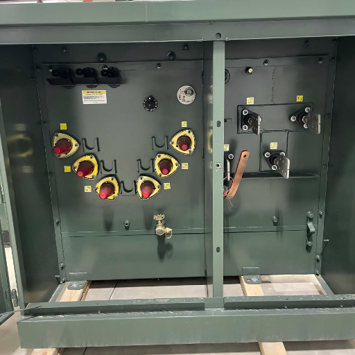
Primary (Medium Voltage) Connections
Route primary cables through the HV compartment conduit openings. Terminate on bushings A, B, and C for three-phase units. Use load-break elbows for dead-front designs or porcelain bushings for live-front units as appropriate.
Torque all bushing terminals to manufacturer specifications. Under-torqued connections overheat. Over-torqued connections crack bushings. Mark torqued connections with a paint pen to show they have been checked.
Secondary (Low Voltage) Connections
Connect secondary cables to terminals X1, X2, X3, and X0 (neutral). Use properly rated compression lugs sized for the cable and terminal material. Spade terminals are common for low-voltage bushing connections.
Support cables independently of the bushings. Mechanical stress on bushings causes gasket failure and eventual oil leaks. Use cable supports or trays inside the compartment to carry the cable weight.
Torque Specifications and Sealing
Torque values vary by manufacturer and hardware size. Typical ranges for pad mounted transformer connections are:
| Connection Type | Typical Torque Range |
|---|---|
| HV bushing terminals | 25-45 lb-ft |
| LV bushing terminals | 15-30 lb-ft |
| Ground lugs | 10-20 lb-ft |
| Cabinet bolts | 5-10 lb-ft |
Always verify actual values against the manufacturer’s installation manual. See the Eaton pad mount transformer installation manual for detailed torque tables and tilt specifications. After torquing, seal cable entry points and compartment doors to prevent moisture ingress.
Common Installation Mistakes to Avoid
Experience shows that most installation problems fall into a few predictable categories. Knowing them in advance prevents rework.
Foundation and Leveling Errors
Eyeballing pad level is the most common leveling mistake. A pad that looks flat can easily exceed 2 degrees of tilt. Always use a precision level or digital inclinometer. Another frequent error is pouring the pad too small. The transformer overhangs the edge, creating a trip hazard and compromising structural support.
Grounding and Bonding Shortcuts
Some crews ground only the tank and skip the doors. Others use a single ground rod instead of a grid. These shortcuts create shock hazards and usually fail utility inspection. Bond every metallic component that could become energized.
Cable Stress and Bushing Damage
A contractor in Arizona once pulled secondary cables tight to make them look neat. Thermal expansion over the first summer cycle stressed the LV bushings. By autumn, two bushings showed oil seepage. The repair required de-energizing the unit, draining oil, and replacing gaskets. Leave adequate cable slack inside the compartment to accommodate thermal movement.
Skipping Pre-Energization Tests
Utility inspectors increasingly require test documentation before sign-off. Skipping insulation resistance or turns ratio tests forces a second inspection visit. Budget time for testing in the project schedule.
Testing and Commissioning
Testing validates that the transformer is ready for service. Do not rush this phase.
Pre-Energization Electrical Tests
Perform these tests before requesting utility inspection:
- Insulation Resistance Test (Megger): Measure winding-to-ground and winding-to-winding resistance. Compare values against manufacturer standards and IEEE C57.12.00.
- Transformer Turns Ratio (TTR): Verify that the actual ratio matches the nameplate. This confirms proper internal connections and tap settings.
- Winding Resistance: Check for loose connections, broken conductors, or incorrect internal jumpers.
- Continuity and Polarity: Confirm that phasing and polarity match the system design.
Record all test results on standardized forms. Utilities typically require signed test reports from a qualified technician.
Oil Quality Checks (for Liquid-Filled Units)
For oil immersed transformer designs, test the dielectric fluid before energization. Check dielectric strength, moisture content, and acidity. New oil should meet ASTM D3487 specifications. If the unit shipped without oil and was filled on site, verify that the filling procedure followed manufacturer vacuum and temperature requirements
No-Load Energization and Monitoring
Energize the transformer with no load for 10 to 15 minutes. Monitor for abnormal noise, vibration, or temperature rise. Compare sound level against NEMA TR1 limits. Record secondary voltage at each phase and adjust tap settings if voltage is outside the acceptable band.
Once no-load stability is confirmed, apply load gradually. Monitor current balance and temperature for the first 24 hours of operation.
If you are sourcing a distribution transformer for a utility or industrial project, request factory test reports and installation documentation with your quotation. Complete documentation reduces commissioning time and inspection risk.
Utility Coordination and Final Sign-Off
The utility or authority having jurisdiction (AHJ) must inspect and approve the installation before final energization. Coordinate this process early.
Inspection Scheduling
Submit inspection requests before installation starts. Many utilities have backlogs of several days to several weeks. Scheduling the inspection for the day after testing is complete avoids standby charges for crews waiting on the inspector.
Have all documentation ready for the inspector. This includes:
- As-built single-line diagram
- Factory test reports
- Site ground resistance test record
- Pre-energization test results
- Nameplate photograph
- Proof of proper grounding and bonding
Documentation Handover
The facility needs complete documentation after approval which should be delivered to the facility owner and maintenance team. The documentation must contain torque records and test results and tap settings and as-built drawings. Good documentation makes future maintenance easier and supports warranty claims if issues arise.
The Midwest utility reported that installations which have complete factory documentation achieve 94% first visit inspection success. Projects with missing test reports or incorrect nameplate data require return visits in nearly half of cases.
Conclusion
Pad mounted transformer installation succeeds when preparation, precision, and testing come together. The five principles that prevent the most problems are:
- Confirm voltage, taps, and vector group before ordering
- Pour a level, reinforced pad that extends at least 6 inches beyond the unit base
- Ground the tank, neutral, and doors to a tested ground grid
- Support cables independently to prevent bushing stress
- Complete pre-energization testing and coordinate utility inspection before energizing
Installation quality directly affects transformer lifespan, efficiency, and safety. A few hours of careful preparation and testing prevent days of costly rework.
Send your project voltage, kVA, and site conditions to Shandong Electric Co., Ltd., a leading transformer manufacturer, for a factory-direct pad mounted transformer quotation with custom solutions and complete installation documentation.
For a deeper technical breakdown of accurate transformer kVA and MVA rating selection methods, see our Transformer Ratings Explained: How to Select the Right kVA or MVA for Your Project.