
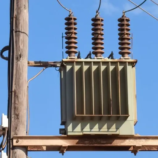
Distribution Transformers: Complete Selection Guide for Industrial Applications

Manufacturing firms in Southeast Asia faced a major operational decision during their last quarter, which would affect their business activities throughout the upcoming three decades. The distribution transformer had reached its end-of-life status so the procurement team needed to decide between selecting a standard-efficiency unit that cost 1000 and a premium-efficiency model, which required 500 extra expense. The purchasing manager favored the cheaper option until the engineering team calculated the 30-year total cost of ownership. The “expensive” transformer would save over 10,000 in energy costs alone, which enabled it to pay for itself within six years.
Industrial facilities throughout the world experience this situation on a daily basis. Your organization will face a major infrastructure decision when selecting a distribution transformer because this choice will determine operational costs, system reliability, and workplace safety for the upcoming years. Understanding proper transformer specification procedures becomes essential for your manufacturing plant expansion, utility substation upgrade, and new data center design projects.
The distribution transformer technology fundamentals, available transformer types, selection process, and actual ownership costs will be taught through this detailed guide. You will acquire the expertise needed to select the best transformer solution for any situation by the end of this program.
What Is a Distribution Transformer?
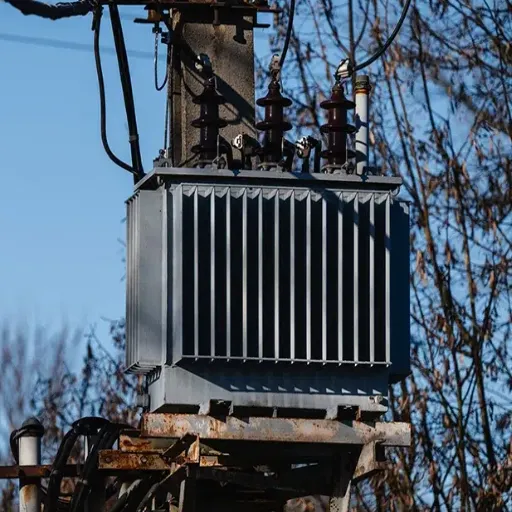
A distribution transformer is a static electrical device that steps down high-voltage electricity from transmission systems to lower voltages suitable for commercial, industrial, or residential use. These transformers use electromagnetic induction to transfer electrical energy between circuits by means of a common magnetic field, which allows them to convert voltage without using mechanical components.
Distribution transformers operate with primary voltages up to 33 kV and secondary voltages of 230V or 415V, while power transformers handle bulk transmission at voltages that exceed 66 kV. The equipment operates continuously at changing load conditions, which enables it to function as the last power delivery component that supplies electricity to customers.
How Distribution Transformers Work
The basic function of the system depends on Faraday’s Law of electromagnetic induction. The primary winding generates a magnetic field that oscillates through the laminated steel core when alternating current passes through it. The secondary winding receives an induced voltage from the magnetic flux that flows through it. The voltage transformation ratio equals the ratio of turns between the windings:
V_secondary / V_primary = N_secondary / N_primary
Step-down distribution transformers use fewer secondary winding turns than primary winding turns, which produces a lower output voltage. Modern units achieve efficiency ratings exceeding 99% for larger capacities with minimal energy loss during conversion.
Key Components
The core of the system uses grain-oriented electrical steel laminations, which create a path for magnetic flow between primary and secondary windings.
The winding system consists of copper and aluminum conductors, which form primary high-voltage coils and secondary low-voltage coils. The electrical conductivity of copper surpasses that of aluminum, yet leads to higher expenses, whereas aluminum enables cost reduction through larger conductor dimensions.
The insulation system uses Class F materials, which withstand 155°C, and Class H materials, which withstand 180°C, to prevent electrical shorts while ensuring reliable operation during thermal stress conditions. Oil-immersed units use mineral oil or ester fluids for both insulation and cooling.
Oil-immersed transformers use dielectric fluid to remove heat, whereas dry-type transformers depend on air circulation and resin-based encapsulation for cooling purposes.
Bushings and terminals function as insulated conductors that create electrical links but keep themselves separate from the tank or enclosure. The pad-mounted units use dead-front designs, which improve their safety features.
The protection devices include Bay-O-Net fuses, pressure relief valves, Buchholz relays for oil-immersed systems, and temperature monitors, which protect against faults and abnormal operating conditions.
Distribution Transformer vs. Power Transformer
Understanding the distinction between distribution and power transformers is crucial for proper specification. While both operate on electromagnetic induction principles, their design philosophies and applications differ significantly.
| Characteristic | Distribution Transformer | Power Transformer |
|---|---|---|
| Voltage Range | Up to 33 kV primary | 66 kV to 765 kV+ |
| Capacity Range | 10 kVA to 5,000 kVA | 5 MVA to 1,000+ MVA |
| Design Efficiency | Optimized for 50-70% load | Optimized for a near 100% load |
| Load Variation | High fluctuation (residential/commercial) | Relatively constant (grid transmission) |
| Size and Weight | Compact, manageable | Very large, specialized transport required |
| Insulation | Distribution class BIL | High-voltage BIL requirements |
| Tap Changer | Off-circuit or limited on-load | Full on-load tap changing (OLTC) |
The design of distribution transformers needs to achieve maximum efficiency because actual power requirements change throughout the day. The transformer, which supplies power to a residential area, maintains 30% capacity during daytime hours but operates at 80% capacity during peak evening times. The design of core and winding components needs to address the variable load profile, which demands loss reduction at low operating conditions.
Power transformers, in contrast, achieve their highest efficiency when operating at full load or near full load because transmission systems maintain consistent capacity factors throughout their operation. The system design focuses on loss reduction during sustained high-power transfer operations instead of achieving optimal performance at different load levels.
When to Use Each Type
Choose Distribution Transformers For:
- Final voltage step-down to utilization levels
- Applications with variable load profiles
- Local distribution networks serving multiple customers
- Ratings below 5 MVA
- Installations requiring a compact footprint
Choose Power Transformers For:
- Bulk power transmission between substations
- Grid interconnection and voltage transformation
- Applications with stable, continuous high loads
- Ratings above 5 MVA
- High-voltage applications (66 kV and above)
Types of Distribution Transformers
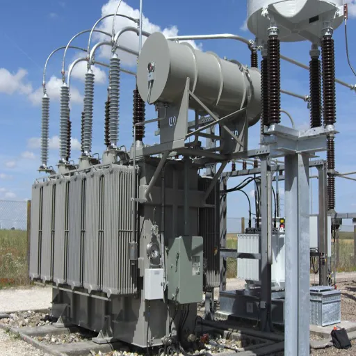
Selecting the appropriate distribution transformer type requires understanding the available configurations and their optimal applications. The three primary classification dimensions are phase configuration, installation method, and cooling/insulation type.
By Phase Configuration
Single-Phase Distribution Transformers
Single-phase transformers supply power for residential use, rural electrification, and light commercial operations. The standard range of capacities extends from 10 kVA to 167 kVA, whereas 25 kVA and 50 kVA, and 100 kVA represent common operating capacities. The transformers establish a connection between one phase and the neutral point, which produces a 230V (international) and 240V (North America) output.
Distribution systems commonly use pole-mounted transformers, which serve as their typical installation method. A utility might install a 50 kVA single-phase transformer to serve 8-12 homes in a residential neighborhood, sized to handle simultaneous peak demand with appropriate diversity factors.
Three-Phase Distribution Transformers
Three-phase transformers supply power to commercial buildings, industrial facilities, and urban distribution networks. The equipment supports operation from 25 kVA to above 5,000 kVA, while its standard ratings include 315 kVA, 500 kVA, 1,000 kVA, 1,500 kVA, and 2,500 kVA. The equipment provides 415V (400V) three-phase power, which enables 230V phase-to-neutral power distribution.
Industrial applications typically require three-phase service for motors and heavy equipment. A mid-sized manufacturing facility with multiple production lines requires a 1,000 kVA unit, whereas a small data center or large commercial complex requires a 2,500 kVA transformer.
Want to understand the specific requirements for your facility? Contact our engineering team for a load analysis and transformer sizing recommendation tailored to your application.
By Installation Method
Pole-Mounted Transformers
Pole-mounted transformers need installation on utility poles that reach a height range of 18 to 25 feet above the ground. The transformers operate within a power range of 16 kVA to 315 kVA, yet users find it harder to acquire transformers that exceed 100 kVA due to their structural limitations.
Advantages:
- Lower installation cost (40-60% less than pad-mounted)
- The system needs less space for installation
- The elevated design protects the system from flood damage
- The design functions as the established standard for overhead distribution systems
Considerations:
- The weather conditions demand that tanks have strong protective features
- Maintenance requires bucket trucks or climbing equipment
- The system creates an aesthetic disturbance that affects the visual appearance of the neighborhood
- The system operates within a specific range of capacity that it can handle
Pad-Mounted Transformers
Pad-mounted transformers need installation on concrete pads at ground level, which they use as their base for installation inside steel cabinets that secure their equipment with locked and tamper-proof protection. The systems operate as underground distribution systems, which support power capacities that range between 75 kVA and 5,000+ kVA.
Advantages:
- The system needs ground-level access, which makes maintenance work easier to perform
- The dead-front design of the system provides improved safety features
- The system can handle more power than the system used for pole-mounted transformers
- The design meets aesthetic requirements for urban settings
- The system works together with underground cable systems
Considerations:
- The system needs higher upfront expenses because it requires both pad construction and cabinet installation
- The system needs to provide maintenance staff with enough space to perform their duties
- The system requires concrete pad installation time, which extends until the concrete reaches its full strength
- The system needs to address potential flood issues because it operates at ground level
In 2023, a commercial development in Austin, Texas, faced a choice between extending overhead lines with pole-mounted units or installing underground distribution with pad-mounted transformers. The developer spent an extra 0,000 for the pad-mounted solution, yet he regained his expenses through increased property value, and he avoided the visual restrictions that affected leasing at a nearby property that used overhead lines as its power supply system.
By Cooling and Insulation Type
Oil-Immersed Transformers
Oil-immersed transformers use mineral oil or synthetic ester fluid as both insulation and cooling medium. The fluid circulates naturally (ONAN – Oil Natural Air Natural) or with pumps and fans (ONAF – Oil Natural Air Forced) to dissipate heat. This design dominates the market with 64.21% market share as of 2025.
Advantages:
- Superior heat transfer enables compact design
- Excellent dielectric properties
- Lower cost per kVA than dry-type
- Proven reliability over decades of service
- Self-healing minor insulation damage
Considerations:
- Fire risk requires separation from buildings (typically 5+ meters)
- Environmental regulations for spill containment
- Requires oil testing and maintenance
- Not suitable for indoor installation without special measures
Dry-Type (Cast Resin) Transformers
Dry-type transformers use air or forced air for cooling, with windings encapsulated in epoxy resin. This design eliminates flammable liquids, making it ideal for indoor installations and fire-sensitive environments. The segment is growing at 8.76% CAGR, faster than oil-immersed units.
Advantages:
- No fire hazard enables indoor installation
- Environmentally friendly (no oil spill risk)
- Virtually maintenance-free operation
- Lower installation costs (no fire protection systems)
- Suitable for sensitive environments (hospitals, schools, high-rises)
Considerations:
- 30-50% higher initial cost than oil-immersed
- Larger physical size for equivalent capacity
- Slightly lower efficiency (0.5-1% difference)
- Limited overload capability
- Higher noise levels
Amorphous Core Transformers
Amorphous core transformers replace conventional grain-oriented silicon steel with amorphous metal ribbon. This advanced material reduces core losses (no-load losses) by 30% compared to traditional CRGO steel.
Advantages:
- Significant energy savings over transformer lifetime
- Reduced carbon footprint
- Fast payback in high energy-cost regions
- Ideal for solar and renewable integration applications
Considerations:
- 15-25% premium over standard efficiency units
- Slightly larger physical dimensions
- Longer lead times for specialty cores
- Limited supplier base
Application Selection Matrix
| Application | Recommended Type | Typical Capacity | Key Considerations |
|---|---|---|---|
| Rural residential | Oil-immersed, pole-mounted, single-phase | 10-50 kVA | Cost-effective, overhead lines |
| Suburban neighborhood | Oil-immersed, pad-mounted, three-phase | 75-500 kVA | Underground distribution, aesthetics |
| Commercial building | Oil-immersed or dry-type, pad-mounted | 500-2,000 kVA | Fire codes, indoor/outdoor placement |
| Industrial facility | Oil-immersed, pad-mounted, three-phase | 1,000-5,000 kVA | Load profile, power quality |
| Data center | Dry-type, pad-mounted | 2,000-5,000 kVA | Fire safety, redundancy requirements |
| Hospital/medical | Dry-type, indoor | 500-2,000 kVA | Critical load reliability, fire safety |
| Solar/wind farm | Amorphous core or high-efficiency oil | 1,000-3,000 kVA | Efficiency priority, bidirectional power |
How to Select a Distribution Transformer
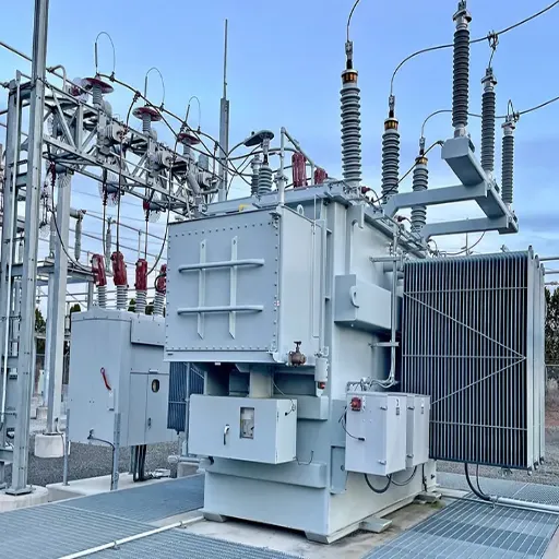
Proper transformer selection requires a systematic analysis of electrical requirements, environmental conditions, and economic factors. Following a structured approach ensures optimal specification.
Step 1: Calculate Required Capacity
The correct calculation of capacity prevents both undersizing, which causes equipment to fail early and oversizing, which leads to inefficient operations and financial losses.
The Capacity Formula:
Required kVA = (Total Connected Load kW × Demand Factor) / Power Factor
Where:
- Total Connected Load: Sum of all equipment ratings
- Demand Factor: Accounts for non-simultaneous operation (typically 0.6-0.8 for industrial, 0.4-0.6 for residential)
- Power Factor: Ratio of real power to apparent power (typically 0.85-0.95)
Example Calculation:
Consider a manufacturing facility with the following equipment:
- Production machinery: 600 kW
- HVAC systems: 150 kW
- Lighting: 80 kW
- Office equipment: 50 kW
- Total connected load: 880 kW
The demand factor of 0.75 was applied to the total equipment load because not all equipment would operate at once. The power factor was assumed to be 0.9.
Required kVA = (880 × 0.75) / 0.9 = 733 kVA
The future expansion demand has been calculated by adding 25% to the current needs. 733 × 1.25 = 917 kVA
The standard selection process requires the use of a 1,000 kVA transformer.
Distribution transformers achieve their highest efficiency when they operate between 50% and 70% of their rated capacity. The selection of a unit that will be used mostly within this operational range will produce the best results for energy cost management.
Step 2: Determine Voltage Requirements
Primary Voltage
Match the available utility supply voltage. Common distribution levels include:
- 6.6 kV (older systems, some international)
- 11 kV (common in many international markets)
- 22 kV (increasingly common for new installations)
- 33 kV (higher-density urban areas)
Confirm the nominal voltage and acceptable range with your utility provider. Some utilities specify tight voltage tolerances requiring tap changers.
Secondary Voltage
Standard secondary configurations include:
- 230V/400V (three-phase, 50 Hz, international standard)
- 240V/415V (three-phase, 50 Hz, Australian/Asian variants)
- 277V/480V (three-phase, 60 Hz, North American commercial)
- 120V/208V (three-phase, 60 Hz, North American small commercial)
Winding Configuration
The vector group specifies primary and secondary winding connections and their phase relationship. For distribution transformers, Dyn11 is most common:
- Primary: Delta (D) connected
- Secondary: Wye (y) connected with neutral brought out (n)
- Phase shift: 11 o’clock position (330° lag)
This configuration provides:
- Neutral availability for single-phase loads
- Phase shift that reduces harmonic propagation
- Ground fault current path
Step 3: Select Cooling and Insulation Type
Transformers are selected based on their installation location, their safety needs, and the environmental laws that apply to the installation site.
Select Oil-Immersed When:
- The outdoor space needs to have at least 5 meters of clearance from structures
- The available budget limits all spending
- The system needs to operate at its highest possible performance level
- The organization can conduct oil tests for maintenance tasks
- The organization needs to maintain the required fire separation distances
Select Dry-Type When:
- The installation must take place inside buildings
- The installation needs to protect against fire hazards that endanger people in hospitals, schools, and high-rise buildings
- The environmental regulations stop the use of oil-filled equipment
- The installation site exists close to water bodies and sensitive environments
- The organization needs to keep equipment operating without interruption
Environmental Considerations
For oil-immersed units, evaluate:
- Soil conditions (permeability and groundwater table)
- Spill containment requirements
- Local regulations (some jurisdictions mandate dry-type indoors)
- Temperature extremes (low temperatures affect oil viscosity)
Step 4: Specify Efficiency Requirements
Transformer efficiency standards have tightened significantly, with regulatory requirements varying by region.
United States DOE Standards
The Department of Energy established efficiency minimums effective January 2016, with additional tightening proposed for 2029:
| Capacity | DOE 2016 (Minimum) | DOE 2029 (Proposed) |
|---|---|---|
| 150 kVA | 98.78% | 98.95% |
| 500 kVA | 99.18% | 99.35% |
| 1,000 kVA | 99.27% | 99.42% |
| 2,500 kVA | 99.52% | 99.60% |
International Standards
- IEC 60076: International Electrotechnical Commission standards for power transformers
- GB 20052: Chinese national standard with tiered efficiency grades (Tier 1 highest)
- EN 50541: European standard for distribution transformers
Premium Efficiency Considerations
Specifying efficiency above minimum standards adds 15-25% to initial cost but delivers:
- 20-30% reduction in no-load losses
- 10-15% reduction in load losses
- 5-10 year simple payback period
- Significant lifetime energy cost savings
For a 1,000 kVA transformer operating at 60% load with electricity at 0.10/kWh, upgrading from standard to premium efficiency saves approximately 500 annually in energy costs.
Step 5: Address Special Requirements
Impedance Voltage
Impedance (expressed as a percentage) determines:
- Short-circuit current magnitude
- Voltage regulation under load
- Parallel operation capability
Standard impedance for distribution transformers ranges from 4% to 6%. Higher impedance limits fault current but increases internal voltage drop. Coordinate with protective device settings and upstream fault levels.
Tap Changers
Off-circuit tap changers (manual switching with de-energization) provide ±2.5% or ±5% voltage adjustment. On-load tap changers (OLTC) enable automatic adjustment under load but add complexity and cost rarely justified for distribution applications.
Protection Requirements
Specify required protective devices:
- Internal fuses (Bay-O-Net, ELSP)
- Pressure relief devices
- Temperature monitoring (oil or winding)
- Gas detection (Buchholz relay for oil-immersed)
- Surge protection (lightning arresters)
Sound Level
Noise limits may apply in residential or noise-sensitive areas. Standard transformers produce 55-65 dB at 1 meter. Low-noise designs (45-55 dB) are available at premium pricing.
Energy Efficiency and Total Cost of Ownership
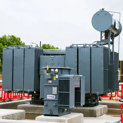
When evaluating distribution transformers, purchase price represents only 15-20% of the total cost of ownership over a 30-year service life. Energy losses account for 60-70% of lifecycle costs, making efficiency specifications critically important.
Understanding Transformer Losses
No-Load Losses (Core Losses)
The system experiences no-load losses, which persist throughout the entire day because the system remains operational without any interruption. The losses occur because the core requires magnetic field activation to function, which results in:
- Hysteresis losses: Energy consumed reversing magnetic domains
- Eddy current losses: Circulating currents induced in the core laminations
A 1,000 kVA transformer shows no-load losses between 1,200W and 2,000W because its design determines the specific value. A 1,600W no-load loss will result in energy costs exceeding 000 after 30 years at a rate of 0.10 per kilowatt hour.
The use of amorphous core transformers results in a 30% reduction of no-load losses when compared to standard CRGO steel transformers, which brings important operational cost benefits during periods of minimal use.
Load Losses (Copper Losses)
Load losses depend on the load current squared multiplied by the resistance of the system which occurs only when the transformer operates. The windings create these losses because of their resistance:
Load Loss = I² × R (for each winding)
A 1,000 kVA transformer shows load losses between 10,000W and 12,000W when it operates at its maximum capacity. The load losses at 50% capacity decrease to a range between 2,500W and 3,000W because the losses increase with the square of the current.
Efficiency Standards Comparison
| Standard | Rating Basis | Typical 1000 kVA Efficiency |
|---|---|---|
| DOE 2016 (US) | Minimum at 50% load | 99.27% |
| DOE 2029 (proposed) | Minimum at 50% load | 99.42% |
| NEMA TP-1 | At 35% load | 99.16% |
| IEC 60076-1 | At 100% load | 99.20% |
| GB 20052 Tier 1 (China) | At 100% load | 99.25% |
| Premium efficiency | At 50% load | 99.50%+ |
Note: Efficiency percentages represent total output power divided by input power. A 99.3% efficient 1,000 kVA transformer dissipates 7 kW as heat at full load.
Total Cost of Ownership Analysis
30-Year Cost Breakdown for 1,000 kVA Transformer
| Cost Category | Standard Efficiency | Premium Efficiency |
|---|---|---|
| Initial purchase | 15,000 (18%) | 18,000 (12%) |
| No-load losses (30 yr) | 27,000 (32%) | 18,000 (22%) |
| Load losses (30 yr) | 38,000 (45%) | 50,000 (60%) |
| Maintenance (30 yr) | 4,000 (5%) | 3,000 (4%) |
| End-of-life | 1,000 (1%) | 1,000 (1%) |
| Total 30-Year Cost | 85,000 | 90,000 |
| Savings with Premium | — | 5,000 |
Assumptions: 60% average load, 0.10/kWh electricity, 30-year life
The premium efficiency transformer costs,000 more initially but delivers,000 in lifetime savings through reduced energy consumption.
Calculating Return on Investment
Simple Payback Period:
Payback (years) = Premium Cost / Annual Savings
For the example above: 7,000 / 1,800 = 3.9 years
Net Present Value (NPV):
The premium unit generates energy savings that exceed 1000 when evaluated with a 6% discount rate over 30 years, which makes it a good investment option even though its initial costs are higher.
When Premium Efficiency Makes Most Sense:
- High electricity rates (>. 12/kWh)
- Long operating hours (>6,000 hours/year)
- Higher load factors (>50% average)
- Carbon reduction goals
- Cold climates (waste heat has a negative value)
Standards and Certifications
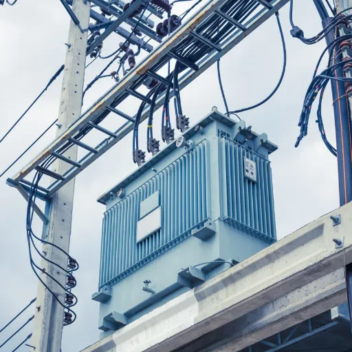
Compliance with recognized standards ensures safety, performance, and interoperability. Understanding relevant standards helps specify appropriate requirements.
International Standards
IEC 60076 Series (International Electrotechnical Commission)
The IEC 60076 series provides the most widely adopted international standards for power transformers:
- The first section, IEC 60076-1, establishes general requirements together with technical specifications.
- The second section, IEC 60076-2, describes methods for measuring temperature increases and cooling systems.
- The third section, IEC 60076-3, establishes standards for insulation testing and dielectric testing procedures.
- The fourth section, IEC 60076-5, tests equipment to determine its short-circuit endurance capabilities.
- The fifth section, IEC 60076-11, describes the specifications and requirements for dry-type transformers.
- The sixth section, IEC 60076-13, describes the requirements for self-protecting liquid-filled transformers.
Key IEC requirements include:
- The first requirement defines temperature rise limits which permit 65°C average winding and 78°C maximum oil-immersed temperature.
- The second requirement needs insulation coordination together with BIL (Basic Insulation Level) ratings.
- The third requirement assesses the equipment’s ability to endure short-circuit conditions.
- The fourth requirement establishes testing protocols for routine tests, type tests, and special tests.
IEEE C57 Series (Institute of Electrical and Electronics Engineers)
The North American market relies mainly on IEEE standards, which have become the primary market standards.
- The standard IEEE C57.12. 00 defines all fundamental requirements for liquid-immersed transformer systems.
- The standard IEEE C57.12. 34 establishes requirements for transformers that use pad-mounted transformer designs.
- The standard IEEE C57.12. 38 defines requirements for transformers that operate under water.
- The standard IEEE C57.12. 51 establishes requirements for ventilated dry-type transformers.
- The standard IEEE C57.110 provides a thermal loading guide for electrical equipment.
The IEEE standards display compatibility with IEC standards yet they introduce distinct requirements for temperature testing and safety assessment.
Regional Requirements
United States
- DOE 10 CFR Part 431: Energy efficiency standards
- UL 1561: Standard for dry-type general purpose transformers
- UL 1562: Standard for distribution transformers
- NEMA TP-1: Guide for determining energy efficiency
- NEMA TP-2: Test procedures
Europe
- EN 50541: Dry-type distribution transformers
- EN 50464: Oil-immersed distribution transformers
- EU Ecodesign Directive: Establishes minimum efficiency requirements that apply to both Tier 1 and Tier 2 testing standards.
- CE marking: Required for products sold in the European Economic Area
China
- GB 1094.1: Power transformers – General
- GB 20052: Minimum allowable values of energy efficiency
- CCC certification: Compulsory for domestic market access
Testing and Documentation
Routine Tests (performed on every unit):
- Winding resistance measurement
- Voltage ratio and phase relationship
- Short-circuit impedance
- Load loss and no-load loss measurement
- Applied voltage and induced voltage tests
Type Tests (performed on representative samples):
- Temperature rise test
- Lightning impulse test (BIL)
- Sound level measurement
Request the following documentation for any transformer purchase:
- Factory test reports
- Material certificates (copper, steel, insulation)
- Compliance certificates (IEC, IEEE, GB as applicable)
- Installation and maintenance manual
- Warranty terms and conditions
Installation and Maintenance Best Practices
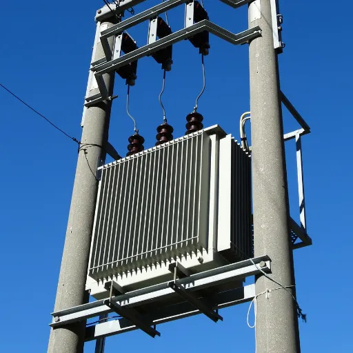
Proper installation and preventive maintenance significantly extend transformer service life and ensure reliable operation. Oil-immersed transformers typically achieve 30-40 year lifespans with appropriate care, while dry-type units average 25-35 years.
Installation Guidelines
Site Preparation
The following specifications for pad-mounted transformers are:
- Concrete pad: Minimum 6-inch thickness with 2,500 psi concrete
- Dimensions: The pattern should extend 6 inches beyond the transformer base on all sides.
- Leveling: The pad surface needs to achieve a level between 1/4 inch throughout its entire area.
- Grounding: The installation of the grounding grid must occur before the construction of the pad.
- Drainage: The pad needs to slope away from the transformer for water to flow away without forming pools.
For pole-mounted transformers:
- Pole strength: The pole needs to support both the transformer weight and the additional weight from wind and ice loading.
- Height: The height needs to reach at least 18 feet, which should measure from the tank’s bottom.
- Access: The area must provide safe access through climbing or a bucket truck for maintenance work.
Electrical Connections
- The verification of phase rotation must occur before the system energizes.
- All connections need to be torqued according to the specifications provided by the manufacturer.
- The installation requires both cable lugs and termination kits that match the specific project requirements.
- The installation of surge arresters needs to occur on the primary power system.
- The system needs to maintain sufficient space for the cables to bend without risk of damaging the equipment.
Grounding Requirements
Proper grounding is essential for safety and equipment protection:
- Tank/enclosure ground: Maximum 5 ohms resistance
- The neutral ground system must exist as a separate entity from the tank ground system.
- The ground conductor needs to be sized according to either NEC standards or the local building code.
- Ground electrodes: Multiple rods in high-resistivity soil
Pre-Energization Checklist
The following steps need to be taken before any new or relocated transformer becomes energized:
- The nameplate ratings need to match the requirements of the particular application.
- The oil level in the oil-immersed system needs to be checked at the temperature-corrected level.
- The inspection should check for damage that might have occurred during shipping.
- The verification process needs to confirm that all protective devices have been installed and configured in their correct operational state.
- The megger test of windings should show results that exceed 500 MΩ at a temperature of 20°C.
- The tap changer position needs to be checked to confirm it matches the system voltage.
- All tools and foreign materials need to be removed from the tank and enclosure.
Maintenance Schedules
Oil-Immersed Transformers
Semi-Annual Inspections:
- The oil level needs to be checked while we adjust the measurement according to the current temperature.
- The process involves checking all areas of the equipment for possible leakages.
- The inspection checks for all exterior damage, including corrosion and other types of damage.
- The system uses temperature sensors to track the current temperature.
- The system shows pressure and vacuum levels through its gauges, which operate only if the system has this feature.
Annual Maintenance:
- The oil dielectric strength test requires a minimum voltage of 30 kV for new oil.
- The test needs Dissolved Gas Analysis (DGA) to operate on units that exceed 500 kVA capacity.
- The bushing needs inspection together with cleaning activities.
- The process requires verification of connection torque to ensure proper installation.
- The testers need to evaluate protection devices through testing procedures.
- The survey uses infrared thermography to inspect the entire area.
5-Year Intervals:
- Oil filtration or replacement if degraded
- Internal inspection (if accessible)
- Tap changer maintenance
- Painting if corrosion is present
Dry-Type Transformers
Annual Inspections:
- Visual inspection of windings and core
- Cleaning of cooling channels and surfaces
- Insulation resistance testing
- Connection torque check
- Temperature monitoring verification
As-Needed Maintenance:
- De-energized cleaning if dust accumulation
- Re-torque connections if loose
- Ventilation inspection
Common Failure Modes and Prevention
| Failure Mode | Percentage | Causes | Prevention |
|---|---|---|---|
| Insulation degradation | 35% | Thermal aging, moisture, oxidation | Temperature monitoring, oil maintenance |
| Bushing failures | 20% | Tracking, contamination, and mechanical stress | Regular cleaning and inspection |
| Tap changer issues | 15% | Mechanical wear, contact deterioration | Regular operation, inspection |
| Overload damage | 15% | Excessive loading beyond the rating | Load monitoring, proper sizing |
| External factors | 15% | Lightning, switching surges, vandalism | Surge protection, security measures |
Dissolved Gas Analysis (DGA)
The DGA system identifies early electrical failures through its method of analyzing transformer oil’s dissolved gas content.
- The presence of hydrogen (H2) indicates corona discharge
- The detection of methane (CH4) shows that the oil has reached its overheating point
- The presence of acetylene (C2H2) indicates that arcing has occurred at its most dangerous level.
- The presence of ethylene (C2H4) shows that paper and insulation materials have reached their overheating state.
The system uses gas concentration data to show which problems will develop in the future, which helps users schedule maintenance work before any equipment fails.
Market Trends and Future Outlook
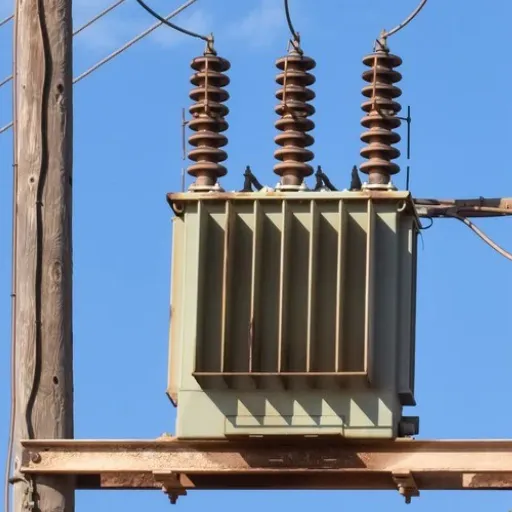
The distribution transformer market is experiencing significant transformation driven by grid modernization, renewable energy integration, and efficiency regulations.
Market Growth Projections
The global distribution transformer market reached USD 43.35 billion in 2026, projected to grow to USD 63.34 billion by 2031 at a 7.88% compound annual growth rate. The following factors drive market growth:
- Developing economies expand their grid infrastructure
- Developed markets replace their old transformer fleets, which average 30 to 40 years of service
- The energy sector requires additional interconnection capacity for renewable energy integration
- Data centers experience increasing power consumption
- Transportation systems and heating systems adopt electric power systems
Technology Trends
Smart Grid Integration
Digital monitoring systems are becoming standard features:
- Real-time temperature monitoring (top oil and winding hot spot)
- Load monitoring and historical trending
- Dissolved gas analysis sensors (online DGA)
- Remote communication via cellular or fiber
These capabilities enable:
- Predictive maintenance based on condition rather than schedule
- Optimized loading based on real-time thermal capacity
- Integration with grid management systems
- Asset management optimization
Energy Efficiency Evolution
The proposed DOE 2029 standards will tighten efficiency requirements by approximately 0.15-0.20 percentage points across the capacity range. While this seems small, the aggregate energy savings across millions of installed transformers are substantial.
Amorphous core technology adoption is accelerating, particularly for:
- Solar farm interconnection
- Utilities with high energy costs
- Customers with carbon reduction commitments
Renewable Energy Integration
Solar and wind power create unique requirements for distribution transformers:
- Bidirectional power flow capability
- Handling intermittent loading patterns
- Harmonic tolerance from inverter-based generation
- Low-voltage ride-through requirements
Transformers serving renewable installations often operate at lower average loads than traditional applications but require designs optimized for these specific duty cycles.
Supply Chain Considerations
The transformer industry has encountered major supply challenges since 2021:
- Lead times currently exceed 18 months for large units that have a capacity of more than 2500 kVA.
- Raw material prices for grain-oriented steel and copper experience price fluctuations.
- The industry faces difficulties because of the existing labor shortfall in specialized manufacturing.
- The grid hardening projects now require more power transformers to meet their requirements.
Project scheduling now requires transformer purchases to be planned 12 to 24 months before the actual need.
Conclusion
The process of choosing a distribution transformer demands that you find a middle ground between technical requirements and financial aspects, and operational needs that will persist over time. The decision made today will impact your facility’s energy costs, reliability, and safety for the next three decades.
Key takeaways from this guide:
- Size appropriately using demand factors and power factor considerations, with 20-30% capacity margin for future growth
- Consider the total cost of ownership, not just the purchase price, as energy losses represent 60-70% of lifecycle costs
- Choose a transformer type that meets your operational environment and safety standards, and efficiency requirements
- Choose the right standards (IEC, IEEE, and GB) according to your market area and customer needs
- Maintenance planning needs to start from the beginning to reach the complete design life of 30-40 years
- The supply chain needs 12-18 months to deliver larger units because of lead times
The manufacturing facility from our opening scenario made the right choice. Their premium-efficiency transformer has been in service for three years now, and the energy savings have already covered one-third of the incremental cost. The engineering team has reported stable voltage regulation, which resulted in improved power quality for sensitive production equipment, while they have experienced zero downtime.
Your transformer selection deserves the same careful analysis. The principles in this guide provide the foundation for an informed decision because you need them to replace aging equipment, expand capacity, or build new infrastructure.
Ready to specify the right distribution transformer for your application? Contact Shandong Electric’s engineering team for personalized technical support, sizing calculations, and competitive quotations tailored to your project requirements.
Frequently Asked Questions
What is the typical lifespan of a distribution transformer?
With proper maintenance, oil-immersed distribution transformers achieve a lifespan of 30-40 years, whereas dry-type transformers have a lifespan of 25-35 years. The service life of an asset improves through oil testing, temperature monitoring, and preventive maintenance activities. Long-lasting performance depends on various factors, which include the intensity of loading, the surrounding temperature, the excellence of maintenance, and the standards of manufacturing.
How do I calculate the right size distribution transformer?
You need to calculate the total connected load in kilowatts, which you multiply by the demand factor that ranges from 0.6 to 0.8 for industrial applications and 0.4 to 0.6 for residential applications. The calculation shows that 800 kW connected load multiplied by 0.75 diversity divided by 0.9 PF results in a base load of 667 kVA; therefore, we need to choose a 1,000 kVA unit, which includes a 25% margin.
Are dry-type transformers less efficient than oil-immersed?
Modern dry-type transformers achieve an efficiency level that ranges between 0.5 and 1 percent of the efficiency level of oil-immersed transformers. The development of cast resin technology, which creates more efficient systems, has allowed the efficiency gap that existed between these two systems to decrease. Many applications show that the small efficiency difference between two technologies becomes balanced with three advantages, which include decreased need for maintenance, total removal of fire hazards, and easier process of installation.
What efficiency standards should I specify?
Maximum efficiency of equipment requires you to use DOE 2029 (US) and IEC 60076-1 Tier 1 (international), and GB 20052 Tier 1 (China) standards for your specifications. These standards ensure no-load losses are minimized, which results in the optimal total cost of ownership over time. Premium efficiency units cost 15-25% more upfront but typically deliver 5-8 year payback through energy savings.
How often should distribution transformers be maintained?
Oil-immersed transformers require visual inspections two times each year, together with annual testing, which includes oil analysis and a complete system assessment. Dry-type transformers need cleaning and inspection every year. The temperature monitoring system should operate continuously while all temperature-related alarms need to be checked immediately. The annual testing of Dissolved Gas Analysis (DGA) needs to be conducted for equipment that exceeds 500 kVA capacity.