
Instrument Transformer CT PT Guide: Selection, Standards, and Procurement

The instrument transformer transforms high voltage or current into safe measurable levels which can be used for equipment metering and protection functions. Current transformers (CT) reduce current to lower values while potential transformers (PT) reduce voltage to lower values, which means that utilities will lose thousands of dollars in revenue through protection systems that fail during faults when, both devices need the correct accuracy class and burden to function properly.
The installation of revenue-metering CTs at a Southeast Asian utility became costly because the utility failed to calculate secondary burden. The CTs experienced a 3% reading error after 200 meters of cable installation between the outdoor switchgear and the control room. Before anyone identified the problem, the small error resulted in unbilled energy worth more than $180,000 for every annual billing cycle. The procurement team made the basic error which they specified the correct ratio yet they failed to calculate burden correctly.
Most substation designers and protection engineers understand what CTs and PTs do. Fewer have a systematic framework for matching accuracy class, ratio, and burden to real applications. The instrument transformer CT PT guide shows you which equipment types and standards exist, together with the selection logic needed to identify equipment that achieves long-term reliable performance.
You will learn how CTs and PTs work, what accuracy classes mean in practice, how to calculate burden, and how to write procurement specifications that protect your project. The principles here will help you reduce specification risk, regardless of whether you are designing a new substation or upgrading switchgear.
For a more in-depth understanding of power transformers, (please refer to our complete guide to power transformers.)
Key Takeaways
- CTs connect in series and step down current to 1A or 5A. PTs connect in parallel and step down voltage to 110V or 100V.
- Metering CTs use Class 0.2S or 0.5S. Protection CTs use Class 5P10, 10P10, or TPY.
- Never open-circuit an energized CT secondary. Never short-circuit an energized PT secondary.
- Burden calculation including cable length is critical; exceeding rated burden destroys accuracy.
- IEC 61869 and IEEE C57.13 are the governing standards. Specify compliance at procurement.
What Is an Instrument Transformer?
Definition and Purpose
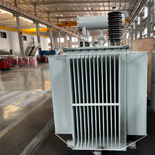
An instrument transformer isolates and scales primary circuit quantities so that meters, relays, and monitoring devices can operate safely. Without instrument transformers, connecting a protection relay directly to a 33 kV line would require insulation and components rated for that voltage, which is impractical and dangerous.
These devices serve two distinct functions. Metering cores deliver precise, proportional signals to energy meters and power-quality analyzers. Protection cores supply protective relays with current or voltage representations that trigger breaker operations during faults. The same physical CT or PT can contain multiple cores, each optimized for one function.
Instrument transformers appear in every medium- and high-voltage installation. You will find them in utility distribution transformers, industrial substations, switchgear assemblies, generator terminals, and renewable energy collection points.
Want to see how instrument transformers integrate with power transformer protection systems? Explore our substation equipment guides.
CT vs PT at a Glance
| Feature | Current Transformer (CT) | Potential Transformer (PT) |
|---|---|---|
| Connection | Series with primary conductor | Parallel across primary voltage |
| Primary quantity | Current (A) | Voltage (V) |
| Secondary rating | 1A or 5A | 110V or 100V typical |
| Function | Steps down current | Steps down voltage |
| Secondary hazard | Never leave open-circuited | Never short-circuited |
| Core material | High-permeability silicon steel | Similar, optimized for voltage |
| Typical use | Ammeters, relays, energy meters | Voltmeters, protection, synchro-check |
This table captures the essential difference, but selection requires deeper understanding of each device.
How Current Transformers (CT) Work
Working Principle and Construction
A current transformer operates on the same electromagnetic principle as any power transformer, but with one critical difference: the primary winding is often just a single conductor passing through the core. The secondary winding has many turns and connects to the measurement or protection circuit.
The primary conductor generates magnetic flux in the core when load current passes through it. The secondary winding converts that flux back into a current proportional to the primary current, reduced by the turns ratio. A 1000:5 CT, for example, delivers 5A secondary when 1000A flows in the primary.
CT construction varies with application. Epoxy-resin cast units dominate indoor switchgear up to 36 kV because they resist moisture and contaminants. Oil-immersed CTs handle higher voltages and outdoor environments. Dry type transformers share similar insulation philosophy with cast-resin CTs, though they serve different functions.
CT Types
| CT Type | Best For | Typical Ratio Range |
|---|---|---|
| Bar-primary | High current, switchgear | 400:5 to 5000:5 |
| Wound-primary | Low current, precision | 10:5 to 200:5 |
| Window / Ring | Retrofit, busbar applications | 200:5 to 3000:5 |
| Split-core | Temporary monitoring, existing cables | 100:5 to 2000:5 |
| Combined CT/PT | Compact switchgear, metering panels | Custom |
Bar-primary CTs are the most common in medium-voltage switchgear. The busbar itself acts as the primary conductor, which eliminates a separate winding and improves reliability. Window-type CTs slip over existing cables when retrofitting protection into an older installation.
Safety: Why You Must Never Open-Circuit a CT
The secondary circuit of a CT must always maintain a low-impedance connection to the ground. The primary current flow through the system creates a magnetic field which collapses when the secondary circuit opens and the current transformer tries to sustain its ampere-turn balance through extremely high voltage production at the open terminals. The voltage reaches thousands of volts which destroys insulation and creates a serious shock hazard.
James, who worked as a commissioning engineer at an African mining project, disconnected a protection CT secondary without turning off power during live testing which resulted in an arc that burned the terminal block and caused the entire feeder to trip. The outage which lasted six hours, stopped production at a facility that generated $40,000 per hour in output. Before you disconnect any device, you must short-circuit the CT secondaries and use shorting blocks or switches that are specifically designed for this purpose.
For a comprehensive breakdown of failure modes and preventive strategies, read our transformer failure causes and prevention guide.
How Potential Transformers (PT) Work
Working Principle and Construction
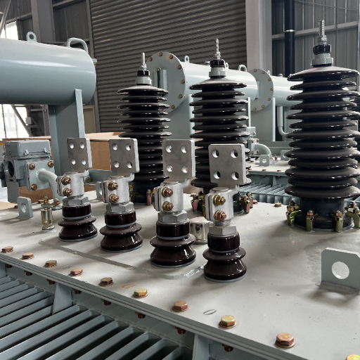
A potential transformer, also called a voltage transformer (VT), connects in parallel with the primary circuit and steps the system voltage down to a standardized secondary level. The secondary typically delivers 110V or 100V, which feeds voltmeters, protective relays, and automatic voltage regulators.
PTs are built like small power transformers, with primary and secondary windings on a common magnetic core. The turns ratio equals the voltage ratio, so a 33 kV / 110V PT has a ratio of 300:1. Because PTs operate at nearly constant voltage, they are designed for low magnetizing current and minimal ratio error under normal operating conditions.
Unlike CTs, PT secondaries present a high impedance to the primary. They draw only a small magnetizing current, which makes them safe to disconnect under normal conditions, provided the secondary is not short-circuited.
PT Types
Electromagnetic PTs use conventional winding and core construction. They are reliable, accurate, and economical for voltages up to about 145 kV. Beyond that, capacitive voltage transformers (CVT) become more practical. A CVT uses a capacitive divider to reduce voltage before a small electromagnetic transformer finishes the step-down. CVTs are lighter, less expensive at extra-high voltage, and can also serve as coupling capacitors for power-line carrier communication.
For most industrial and distribution applications up to 36 kV, electromagnetic PTs remain the standard choice. They offer better transient response and simpler maintenance than CVTs.
Safety: Why You Must Never Short-Circuit a PT
Short-circuiting a PT secondary creates a near-zero impedance across the secondary winding. Because the PT is designed to supply a high-impedance load, a short circuit causes excessive current flow. The resulting overheating can destroy the winding insulation and create a fire risk within minutes. Always verify that PT secondaries are open before energizing, and use properly rated fuses or miniature circuit breakers on secondary circuits.
CT PT Accuracy Classes Explained
Accuracy class is where specification mistakes are most common. A metering CT and a protection CT may look identical on the outside, but their internal design priorities differ dramatically.
Metering Accuracy Classes (0.1, 0.2, 0.2S, 0.5, 0.5S)
Metering CTs prioritize ratio accuracy across the normal load range. Class 0.2S maintains accuracy within 0.2% from 1% to 120% of rated current. The “S” designation means special, and it extends accurate performance down to very light loads. Revenue billing applications almost always specify 0.2S or 0.5S.
Class 0.5 is acceptable for internal energy monitoring where billing precision is less critical. Class 0.1 offers laboratory-grade accuracy for test benches or high-precision power quality studies. Specifying 0.2S when 0.5 would suffice adds cost without benefit. Conversely, specifying 0.5 for a revenue meter can expose a utility to regulatory penalties and revenue leakage.
Protection Accuracy Classes (5P, 10P, TPY, TPZ)
Protection CTs must reproduce fault currents accurately enough for relays to distinguish normal load from dangerous conditions. Class 5P10 means the CT maintains ratio error within 5% at ten times rated current. Class 10P10 allows up to 10% error at the same multiple.
Transient performance classes address high-voltage and generator protection. TPX, TPY, and TPZ are defined in IEC 61869-6 for applications where DC offset during a fault can saturate a standard protection CT. TPY includes a small air gap to reduce remanence, while TPZ has a larger gap optimized for fast transient decay. These classes cost more but are essential for differential protection on large transformers and busbar zones.
PT Accuracy Classes (0.2, 0.5, 3P, 6P)
PT accuracy follows similar logic. Class 0.2 and 0.5 PTs serve metering, with 0.2 used for revenue applications. Class 3P and 6P serve protection, where absolute precision matters less than consistent transformation during faults.
Ratio Error and Phase Displacement
Ratio error is the percentage deviation between actual and ideal secondary current or voltage. Phase displacement is the angular difference between primary and secondary quantities. Both affect transformer efficiency calculations and power-factor measurements. In directional protection schemes, even small phase errors can cause relay misoperation.
| Application | Recommended CT Class | Recommended PT Class |
|---|---|---|
| Revenue metering | 0.2S | 0.2 |
| Substation internal metering | 0.5S | 0.5 |
| Overcurrent protection | 5P10 | 3P |
| Differential protection | 5P20 or TPY | 3P |
| Motor protection | 5P10 | 3P |
How to Select the Right CT and PT
Selection is a five-step process. Skipping any step risks misoperation, poor accuracy, or unnecessary cost.
Step 1: Define Application (Metering vs Protection)
Start by identifying whether the core will feed a revenue meter, a protection relay, or both. Modern switchgear often uses multi-core CTs: one core for metering and another for protection. This separation prevents protection-grade saturation from disturbing revenue measurements.
Step 2: Determine Primary Rating and Ratio
Select a primary rating that covers the maximum continuous load with margin. For metering, the normal operating current should fall between 50% and 80% of the CT primary rating. Operating below 20% of rated current pushes the CT outside its accurate range. For protection, the CT must handle the maximum fault current without saturating within the accuracy limit factor.
The ratio should produce a standard secondary current. Where cable runs exceed 30 meters, 1A secondaries reduce voltage drop and wiring losses compared to 5A.
Step 3: Calculate Burden (VA)
Burden is the total load on the CT or PT secondary, measured in volt-amperes. It includes the impedance of relays, meters, transducers, and the connecting cable.
A typical burden calculation for a CT looks like this:
| Component | VA |
|---|---|
| Energy meter | 2.5 |
| Power analyzer | 1.0 |
| Cable (200m, 2.5 mm²) | 4.0 |
| Contact resistance (terminals) | 0.5 |
| Total | 8.0 |
If the CT is rated 10 VA and the calculated burden is 8.0 VA, the selection is acceptable. If the burden exceeds the rated value, accuracy degrades. This is exactly what happened to the Southeast Asian utility: the CTs were rated 5 VA, but the long cable run pushed actual burden past 8 VA. The solution was either larger conductor, shorter cable, or higher-VA CTs.
Step 4: Select Accuracy Class
Use the table in the previous section to match class to application. For industrial poer distribution, 0.5S metering and 5P10 protection usually suffice. For utility revenue points, specify 0.2S metering. For generator differential protection, specify TPY.
Step 5: Verify Short-Circuit Withstand
The CT or PT must mechanically and thermally withstand the maximum fault current or voltage at the installation point. Verify the dynamic current (I_dyn) and thermal current (I_th) ratings against the substation fault study. A CT that saturates gracefully is useless if the electromagnetic forces tear its windings apart.
Ready to specify CTs and PTs for your project? Send us your primary current, voltage, and burden requirements, and our engineers will confirm ratio and accuracy class recommendations.
CT PT Procurement Best Practices
Standards to Specify (IEC 61869 vs IEEE C57.13)
The existing international standard for instrument transformers is IEC 61869 which replaces the previous IEC 60044-1 and IEC 60044-2 series. The standard defines two accuracy classes together with testing procedures and building specifications. The IEEE C57.13 standard regulates instrument transformers in North America while using a modified system for accuracy class identification.
For international projects, specify IEC 61869 compliance and request a factory test report covering ratio, polarity, excitation characteristics, and winding resistance. For North American projects, specify IEEE C57.13 and require similar documentation. If you are unsure which standard applies, compare the voltage ratio requirements for your specific grid code.
Combined CT/PT Units for Compact Switchgear
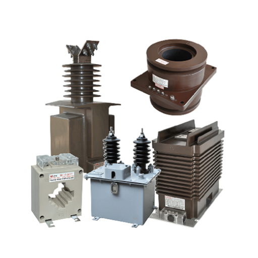
The need for combined CT/PT metering units arises because urban substations and renewable energy skids face space limitations. The devices combine current and voltage transformation functions into one epoxy-resin housing which decreases required space by 40% and removes the need for separate mounting equipment.
The combined units support voltage applications up to 36 kV while providing multiple CT core options and a single PT component. The specification process requires confirmation that the PT section functions without ferroresonance under lightly loaded conditions and proof that CT cores maintain their magnetic independence.
Factory Testing Requirements
Every instrument transformer should leave the factory with documented evidence of performance. Minimum tests include:
- Ratio verification at rated burden
- Polarity check
- Excitation curve (knee-point voltage for protection CTs)
- Winding resistance
- Dielectric withstand (power frequency and impulse)
- Partial discharge (for cast-resin units)
Request these test reports with shipment. They are essential for commissioning verification and future troubleshooting.
Price Ranges by Voltage Class
China-manufactured instrument transformers offer competitive pricing with IEC compliance. Typical B2B ranges are:
| Voltage Class | CT Price (USD) | PT Price (USD) | Combined Unit (USD) |
|---|---|---|---|
| 10 kV / 11 kV | 55−55−180 | 60−60−200 | 50−50−328 |
| 24 kV | 120−120−350 | 130−130−380 | 180−180−450 |
| 33 kV / 36 kV | 200−200−600 | 220−220−650 | 350−350−800 |
| 72.5 kV | $730+ | $750+ | $1,000+ |
Prices vary with accuracy class, burden rating, and number of secondary cores. A 0.2S metering core costs more than a 0.5 core. A TPY protection core costs significantly more than 5P10.
When Maria, a procurement manager for a solar EPC in the Middle East, switched from ordering separate CTs and PTs to combined units for twelve 33 kV substations, she saved 14,000inequipmentcostandanadditional14,000inequipmentcostandanadditional8,000 in mounting hardware and installation labor. The combined units also reduced delivery lead time from ten weeks to seven.
Frequently Asked Questions
What is the difference between CT and PT?
A CT steps down current and connects in series with the primary conductor. A PT steps down voltage and connects in parallel across the primary circuit. CT secondaries produce 1A or 5A. PT secondaries produce 110V or 100V.
Why should a CT secondary never be open?
An open CT secondary generates dangerous high voltage due to loss of ampere-turns balance. This can destroy insulation, damage equipment, and create a severe shock hazard. Always short-circuit CT secondaries before disconnecting any load.
What does 5P10 mean on a protection CT?
5P10 means the CT maintains accuracy within 5% ratio error at ten times the rated current. The “P” stands for protection. Higher numbers like 5P20 allow accuracy at twenty times rated current.
What is the difference between 0.2S and 0.5S CT accuracy?
Class 0.2S maintains accuracy within 0.2% from 1% to 120% of rated current. Class 0.5S allows 0.5% error over the same range. Revenue billing applications require 0.2S. Internal monitoring can use 0.5S.
How do I calculate CT burden?
Add the VA consumption of all connected devices, plus the cable burden (I² x R_cable), plus terminal contact resistance. Compare the total to the CT rated burden. The calculated burden must not exceed the rated value.
What is a combined CT/PT unit?
A combined unit integrates current and voltage transformation in a single housing. It reduces switchgear footprint, simplifies installation, and lowers total cost. Combined units are popular for compact substations and renewable energy projects.
Conclusion
The small size of instrument transformers leads to their ability to create major effects on both metering accuracy and protection system dependability. The incorrect burden rating of a CT causes revenue measurements to become distorted. A protection CT with inadequate accuracy limit factor will fail to trip during a fault. A PT with the wrong class will send misleading voltage signals to critical relays.
The selection framework is straightforward: define the application, size the ratio, calculate burden, choose the accuracy class, and verify fault withstand. The combination of IEC 61869 and IEEE C57.13 compliance needs to be specified while requesting factory test reports and considering combined CT/PT units which need space and cost efficiency.
Every specification decision you make today affects decades of operation. The process of establishing correct specifications begins with the need to understand actual installation meanings of all classes and ratios and burden values.