

Oil Immersed Power Transformer: Complete Technical Guide & Selection Manual

The engineering team found a single specification error that caused the three-month delay of the Bhopal facility upgrade project in 2024. The team selected dry-type transformers for their outdoor substation but failed to consider the extreme summer temperatures that occur in that region. The units experienced overheating during peak load conditions, which resulted in expensive project delays and required urgent system redesigns. The project team used properly defined oil immersed power transformers to solve all thermal problems, which allowed work to continue after two weeks.
Power distribution equipment specification experts know that transformer selection results in project success that lasts for many decades. The global transformer market reached USD 70.90 billion in 2025, with oil immersed designs commanding a significant market share in heavy industrial and utility applications. The procurement teams and engineers face difficulties when they try to understand technical specifications, cooling method options, and IEC 60076 compliance requirements, which help them identify reliable equipment from problematic equipment.
This guide provides the technical depth you need to specify, select, and deploy oil immersed power transformers with confidence. The program will teach you system operations, system performance advantages over dry-type systems, and critical specifications that need maintenance procedures to deliver dependable service across decades.
Want expert guidance for your specific project requirements? Contact our engineering team for customized transformer specifications and application support.
What Is an Oil Immersed Power Transformer?
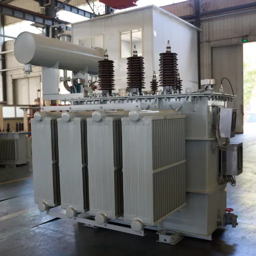
The oil immersed power transformer functions as an electrical device that transmits power between two circuits through electromagnetic induction, while using insulating oil for both dielectric protection and cooling purposes. The system provides enhanced power capacity, efficient heat dissipation, and extended operational lifetime when compared to systems that use air for cooling purposes.
Working Principle and Core Design
The primary operation of the system operates according to Faraday’s principle of electromagnetic induction. The primary winding produces alternating current, which creates a varying magnetic flux that passes through the laminated steel core. The secondary winding receives the induced voltage from the magnetic flux, which enables the system to transform voltage while maintaining power balance, with the exception of operational losses.
The mineral oil filling serves dual critical functions. The first function of the material delivers electrical insulation through dielectric strength, which exceeds 30 kV per 2.5 millimeters of distance, and it prevents arcing between powered electrical parts. The second function of the material serves as a thermal transfer medium, which moves heat from the core and windings to external radiators or tank walls, where it dissipates into the surrounding air.
The longevity of transformers depends on their temperature management. The hot-spot temperature, which represents the highest temperature found in any winding, must stay below 98°C for standard insulation systems according to IEC 60076-2. Insulation damage rates increase at an exponential rate after this limit because insulation damage occurs at the rate of one insulation hour for every 6 to 8 degrees Celsius of prolonged overheating.
Key Components and Their Functions
Core Assembly
The magnetic core consists of grain-oriented silicon steel laminations, which have a thickness range between 0.23 millimeters and 0.35 millimeters. Modern designs use stepped-lap joints and laser-etched domains to reduce no-load losses. Higher-grade core materials create efficiency benefits because they reduce core losses by 15 to 20 percent when compared to standard grades.
Windings
The primary and secondary windings use copper or aluminum conductors, which have paper or enamel coatings for insulation. High-voltage applications use disc-type windings while layer-type configurations suit lower voltages. The vector group designation that distribution transformers use, as Dyn11 shows, is the connection configuration together with the phase displacement between windings.
Conservator and Breather System
Traditional designs include a conservator tank, which needs installation above the main tank for the purpose of handling oil expansion and contraction. The silica gel breather prevents moisture ingress as the oil volume changes. Hermetically sealed designs use corrugated tank walls, which flex with temperature changes to eliminate the need for a conservator system while increasing maintenance efficiency.
Protection Systems
The Buchholz relay detects gas accumulation from internal faults, which provides early warning of incipient problems. Pressure relief devices prevent tank rupture during internal arcing events. Temperature monitors with alarm and trip contacts protect against thermal overload conditions.
Types of Insulating Oil
Mineral Oil
Traditional naphthenic or paraffinic mineral oils comply with IEC 60296 specifications. These materials provide outstanding electrical insulation capabilities together with chemical stability and economical value. The products originate from petroleum sources, yet they create dangerous fire hazards and environmental hazards when spills occur.
Natural Ester Fluids
Vegetable-based ester oils derived from soybean or rapeseed provide biodegradability (over 95% in 21 days per OECD 301) and significantly higher flash points (exceeding 300°C versus 140°C for mineral oil). The properties of ester-filled transformers make them appropriate for indoor use in environments that require fire safety protection. The distribution transformer market shows that 21% of newly installed transformers now operate with ester fluids because environmental regulations and safety concerns drive this trend.
Synthetic Esters
Engineered esters provide fire protection, which natural esters offer, while improving oxidation resistance and expanding operating temperature limits. The high-performance fluids serve demanding needs because their superior reliability justifies their increased starting expenses.
Oil Immersed vs. Dry Type Transformer: Key Differences
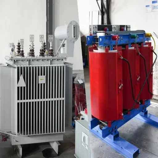
Selecting between oil immersed and dry-type transformer designs requires evaluating performance characteristics, application constraints, and total lifecycle economics. The comparison examines the main factors that people use to make their decisions.
Performance and Capacity Comparison
| Specification | Oil Immersed | Dry Type |
|---|---|---|
| Maximum Voltage | Up to 1,000+ kV | Typically limited to 36 kV |
| Capacity Range | 10 kVA to 500+ MVA | Up to approximately 25 MVA |
| Efficiency | 98.5-99.3% | 97.5-98.7% |
| Overload Capacity | 150-200% short-term | Limited by thermal constraints |
| Service Life | 25-40 years | 15-25 years |
| Noise Level | Higher (oil circulation) | Lower (55-65 dB typical) |
Oil immersed designs excel in high-voltage, high-capacity applications where thermal management challenges intensify. The superior heat transfer capability of liquid cooling enables compact designs that handle overload conditions without performance degradation. Dry-type units, while simpler to maintain, face thermal limitations that restrict their application in heavy industrial and transmission-level deployments.
Safety and Environmental Factors
The main factor that determines safety differences between fire hazards is fire risk. The flammable nature of mineral oil requires fire suppression systems together with oil containment pits and separation from occupied areas according to IEEE 979 and NFPA 850 standards. Natural and synthetic ester fluids create major benefits because their high flash points and low heat release rates serve to alleviate this issue.
The environmental impact assessment shows that dry-type units become the preferred choice in locations that require protection for water sources and safeguarded ecosystems. The use of hermetically sealed oil immersed systems with advanced sealing technology has achieved leak protection because bourbon citrus ester fluids provide environmentally compliant biodegradable solutions.
Commercial buildings, hospitals, and schools require dry-type transformers or ester-filled oil-immersed units because fire codes prohibit other options. Mineral oil immersed systems serve as the main choice for outdoor substations, industrial plants, and utility applications because they allow for affordable implementation of fire safety measures.
Total Cost of Ownership Analysis
Initial Investment
Oil immersed transformers show 15-30% lower prices than dry-type transformers when their capacity ratings match. The cost advantage of oil immersed designs becomes more substantial with higher capacity, which makes them economically attractive for industrial settings that require large equipment.
Installation Costs
The installation of oil immersed systems demands extra facilities, which include oil containment pits, fire walls, and fire suppression equipment. The total installation cost increases by 20-40% through these additions when compared to dry-type systems. The total installation cost of additional infrastructure sometimes gets balanced out by the reduced equipment expenses for the project.
Operating Costs
The design of oil immersed transformers achieves energy efficiency that decreases energy waste throughout the entire lifetime of the transformer. A 1,600 kVA unit at 75% load uses 3,000-5,000 kWh, which creates electricity savings worth USD 300-800 based on local pricing.
Maintenance Requirements
Oil-immersed transformers need regular oil testing, oil filtration, and oil replacement, while dry-type transformers require only visual inspections and cleaning maintenance. The annual maintenance costs for oil immersed units range from USD 500-2,000 based on testing needs and unit capacity, while dry-type equipment maintenance costs USD 200-500. The maintenance expenses for oil immersed units remain 70-80% lower for their entire operational period.
Chen Wei, who works as procurement manager for a Jiangsu manufacturing facility, created a 20-year ownership cost assessment for a 2,500 kVA transformer system when he selected different transformer models for the 2024 expansion project. The oil immersed option, despite higher installation costs, delivered 12% lower total lifecycle costs due to superior efficiency and extended service life expectations.
Selection Decision Framework
Choose Oil Immersed When:
- Installation is outdoors or in dedicated utility rooms with fire protection
- Capacity requirements exceed 2,500 kVA, or voltage exceeds 35 kV
- Ambient temperatures regularly exceed 40°C
- Overload capability is required for intermittent high-demand periods
- Project budget prioritizes equipment cost over installation simplicity
- Long service life (30+ years) is a priority
Choose Dry Type When:
- Installation is indoors near occupied spaces without fire suppression
- Fire codes prohibit flammable insulating materials
- Environmental regulations restrict liquid-filled equipment near water sources
- Capacity requirements are below 2,500 kVA
- Maintenance simplicity outweighs efficiency considerations
- Space constraints prevent oil containment infrastructure
Technical Specifications Explained
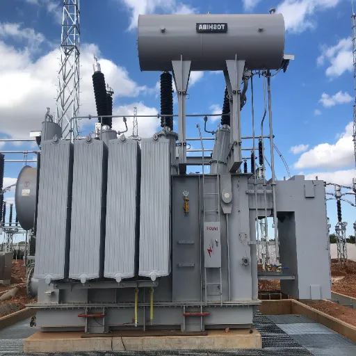
Understanding IEC 60076 standards and transformer specifications enables accurate equipment selection and performance prediction. This section decodes the critical parameters that define transformer capability and compatibility.
Electrical Parameters and Ratings
Rated Power (kVA)
The apparent power rating indicates continuous load capacity under specified temperature conditions. IEC 60076 defines standard ratings in a preferred number series. Selection requires calculating actual load requirements and applying appropriate safety factors. The recommended sizing formula accounts for connected load, power factor, demand factor, and future growth:
Recommended kVA = (Total Connected Load kW / Power Factor) × Demand Factor × Growth Margin
For industrial applications, demand factors typically range from 0.6 to 0.8, depending on load diversity, while growth margins of 20-30% accommodate future expansion without transformer replacement.
Voltage Ratios and Tap Changer Configuration
The primary and secondary voltage ratings must match system requirements with appropriate tolerance for grid variation. On-load tap changers (OLTC) automatically adjust the turns ratio to maintain a constant secondary voltage despite primary voltage fluctuations. Off-circuit tap changers require de-energization for adjustment but offer lower cost and complexity.
Standard tap changer ranges provide ±2×2.5% or ±5% voltage adjustment. OLTC systems use resistor or reactor transition methods, with vacuum interrupters increasingly common for reduced maintenance requirements and extended operating life.
Impedance Voltage (Short-Circuit Voltage)
Impedance voltage, expressed as a percentage of rated voltage, determines the voltage drop under load and limits fault current magnitude. Distribution transformers typically specify 4-6% impedance, while power transformers may require 8-12% or higher to coordinate with protective devices and limit short-circuit stresses.
Higher impedance reduces fault current but increases voltage regulation challenges. Selection requires coordination with system protection engineering to balance fault current limitation with acceptable voltage drop under normal load conditions.
Cooling Methods: ONAN, ONAF, OFAF
IEC 60076 designations define cooling method combinations using a four-letter code system. The first letter indicates the internal cooling medium (O for oil), the second indicates circulation type (N for natural, F for forced), the third indicates external cooling medium (A for air, W for water), and the fourth indicates external circulation method.
ONAN (Oil Natural Air Natural)
Natural convection circulates oil through windings and core, transferring heat to tank walls or radiators where natural air convection provides cooling. ONAN designs suit base-load applications with predictable thermal profiles and represents the most reliable configuration due to the absence of rotating or powered components. Standard distribution transformers up to approximately 10 MVA typically use ONAN cooling.
ONAF (Oil Natural Air Forced)
Fan banks mounted on radiators increase heat dissipation without requiring oil pumps. ONAF cooling typically provides 25-33% additional capacity compared to ONAN ratings for the same physical unit. Control systems activate fans based on oil temperature or load current, providing efficient operation across varying load profiles.
OFAF (Oil Forced Air Forced)
Motor-driven oil pumps circulate oil through heat exchangers while fans cool the external surfaces. OFAF designs enable high power density in large power transformers where natural convection proves insufficient. These systems suit continuous high-load applications such as power plant generator step-up transformers and heavy industrial installations.
ODAF (Oil Directed Air Forced)
Directed oil flow systems pump oil through specific winding cooling ducts, optimizing heat removal from critical areas. ODAF configurations achieve maximum cooling efficiency for ultra-high-capacity units where uniform temperature distribution is essential.
Temperature Ratings and Limits
IEC 60076-2 specifies temperature rise limits referenced to 40°C ambient temperature:
| Location | Temperature Rise Limit | Maximum Temperature |
|---|---|---|
| Top oil (ONAN/ONAF) | 55°C | 95°C |
| Top oil (OFAF/OFWF) | 50°C | 90°C |
| Winding average | 65°C | 105°C |
| Hot-spot | Not specified directly | 98°C (for 20-year life) |
The hot-spot temperature, typically 10-15°C above average winding temperature, represents the critical factor for insulation aging. Modern transformers often include fiber-optic temperature sensors that directly measure hot-spot locations, enabling optimized loading and extended life through intelligent thermal management.
Insulation and Oil Quality Standards
IEC 60076-2: Temperature Rise Specifications
This specification outlines the procedures for testing temperature rise and the criteria for its acceptance. Such tests, which are conducted in the factories, involve loading a transformer to its rated load, after which temperatures are observed as they rise up to some thermal level or equilibrium is reached.
IEC 60296: Mineral Insulating Oils
Standards for the fresh mineral insulating oils include their physical, chemical, and electrical properties. The basic limits of these include:
- Dielectric breakdown voltage: Not less than 30 kV (2.5 mm clearance)
- Moisture content: At supply, should not exceed 30
- Acid value: Not more than 0.01 milligram in one gram of KOH
- Interfacial tension: Not less than 40 mN/m
IEC 61099: Synthetic Organic Esters
The standards for synthetic esters insulating liquids apply to those used in transformers where mineral oil is not appropriate for fire hazard or environmental reasons. Such liquids allow full functionality in broader temperature ranges and have the ability to degrade.
IEC 62770: Natural Esters
This specification accounts for those natural ester-based fluids that are refined from plants. Oil Immersed Power Transformer has these design capabilities, providing the highest rated fire protection, compatibility with the environment, along with good electrical characteristics for the normal range of work of the distribution or mid power transformers.
Industrial Applications & Selection Guide
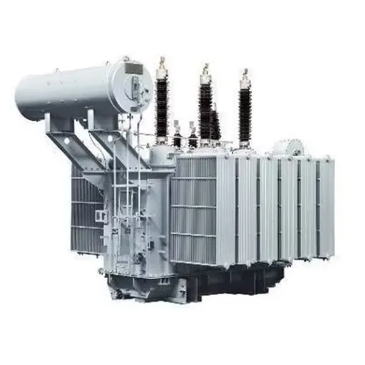
Oil immersed power transformers serve critical functions across diverse industrial sectors. Understanding typical applications and selection criteria enables appropriate specification for specific operational requirements.
Primary Application Sectors
Electric Utility Substations
Electric utility substations that rely mostly on oil-immersed transformers are used for the purpose of power conversion among transmission and distribution levels, which is between 66kV and 400kV and 11kV and 33kV, respectively. These types of installations are designed mainly for reliability, efficiency, and overload capabilities, which are very crucial for grid stability. Rating ranges are up to 10 to 500 MVA with ONAF and OFAF cooling.
Heavy Manufacturing and Process Industries
Oil-immersed transformers are preferred in industries like metals, cement, chemicals, and petrochemicals for this type of distribution, as they need strong power distribution with high short-circuit withstand capability. This ensures that such transformers work well in cases of harsh duty cycles, downturns due to harmonic load, and even some atmospheric conditions that are sometimes known to affect the health of transformers installed in other settings. Often, plant installations cater to special features such as K-factor ratings that transform the load for non-linear items or dual secondary configurations that convey process flexibility.
Mining and Extractive Industries
Underground mining operations and forms of surface mining, in particular coal mining, require substantial mining transformers that can endure vibration, dust, and lack of maintenance access. Specifically structured mining-duty transformers are equipped with reinforced tanks, solid bracing, and protective relays suitable for hazardous environments. Usually, mobile substations with oil-immersed transformers are used to cater to flexible power distribution during mining front advancements.
Renewable Energy Integration
Step-up transformers are required in solar farms and wind generation facilities to connect distributed generation to collection systems and transmission grids. Such applications frequently require the newest developments in focusing for minimal losses to improve energy yield and very specialized vector groups for the mitigation of harmonic content from power electronic converters.
Data Centers and Critical Facilities
Highly-sized scaled facilities call for oil-immersed for the main power transformations, while the prediction of dry or ester -filled transformers by indoor data centers. Surely, oil temperature improves the loss level and system efficiency, except for the presence of the ester type. By this, all requirements are met; however, in fire protection infrastructure, such huge data centers require internal fire protection for oil transformers and a higher fire grade.
Sizing and Specification Process
Step 1: Load Analysis and Characterization
Record all connected loads individually with their kW ratings, power factors, and duty cycles. Look into starting characteristics of motors because you will need oversized transformers or a special impedance design due to extremely high inrush currents with respect to each load. Analyze the harmonic content for VFD and power-electronic loads that were numerous.
Step 2: Calculate Required Capacity
Apply the sizing formula with appropriate factors:
- Connected Load: Forming the sum plates of the names of all equipment.
- Demand Factor: Industrial: 0.6-0.8 and Commercial: 0.4-0.6
- Power Factor: Typically about 0.85-0.95.
- Growth Margin: Luxurious or optional 20 to 30% in expansion capacity
Example calculation for a manufacturing facility:
- Connected load: 2,000 kW
- Power factor: 0.9
- Demand factor: 0.75
- Growth margin: 1.25
Required kVA = (2,000 / 0.9) × 0.75 × 1.25 = 2,083 kVA
Standard rating selection: 2500 kVA (next standard size above calculated requirement).
Step 3: Specify Electrical Characteristics
- Primary voltage: Interface with available utility supply
- Secondary voltage: Interface with facility power distribution system
- Vector group: Dyn11 specified. This will help to avoid neutral shift and will take care of harmonics.
- Impedance: Confirm with protection coordination study. The typical value for this size would be 6%.
- Tap changer: OLTC drive should prevent deviations in primary voltage exceeding ±5%.
Step 4: Define Environmental and Installation Conditions
- Altitude Deration: 0.4% capacity decrease per 100 m above 1,000 m
- Ambient temperature: Standard design rated at 40°C max
- Seismic: High-risk zones require special bracing
- Ingress protection: IP55 outdoor area, at least, with IP65 for harsh environments
Step 5: Select Optional Features
- Cooling: ONAN normal. Specify ONAF for cyclic loading with high instantaneous current inputs
- Oil type: Generic transformer oil for standard application, ester for additional safety improvements
- Monitoring: Temperature sensors, DGA ports, and bushing monitoring
When Liu Ming, project engineer for a chemical processing plant in Shandong, decided which transformers to use for their facility upgrading by 2025, he took the ester fluid filling as the priority despite the higher cost of 15% to the initial estimates. Mitigation of environmental risks was top-notch in their new proximity to estuarine lands located, while, importantly, the ester fluid served as yet another protection against possible spills.
Installation & Maintenance Best Practices
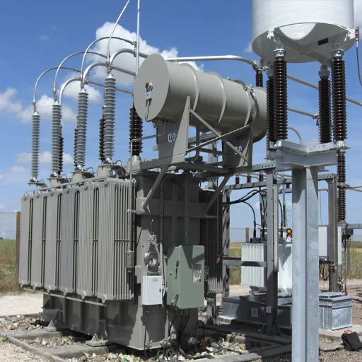
Proper installation and systematic maintenance ensure reliable operation across the transformer design life. This section covers essential requirements and best practices derived from IEC and IEEE standards.
Installation Requirements
Foundation and Mounting
Transformers require a reinforced concrete foundation that can safely carry the complete weight and dynamic loads from earthquakes or short-circuit forces. A 2,500 kVA unit is generally equivalent to 4-6 metric tons, whereas large power transformers may weigh more than 100 metric tons. Raised access flooring must contain provisions for drainage so as to prevent water accumulation and also comply with electrical clearances above ground level.
Clearances and Access
Installation must provide minimum clearances for safe operation and maintenance access:
- Front (bushing side): 1.5-2.0 meters minimum
- Rear and sides: 1.0 meter minimum
- Top: Adequate clearance for lifting equipment during installation and maintenance
- Oil containment: Volume sufficient for total oil quantity plus rainfall capacity
Fire Safety Infrastructure
Mineral oil installations require:
- Oil containment pit or drainage system with oil separation
- Fire-rated barriers separating transformers from buildings or other equipment
- Automatic fire detection and suppression systems for critical installations
- Emergency response plans and personnel training
Electrical Connections
Bushings must align with incoming and outgoing cable or bus duct routing. Phase sequence and rotation require verification before energization. Grounding connections must meet IEEE 80 or local standards for safety and lightning protection.
Pre-Energization Testing
Commissioning tests verify installation integrity:
- Insulation resistance measurement (megger test)
- Turns ratio verification
- Winding resistance measurement
- Oil dielectric testing
- Protection relay functional testing
- Thermal imaging survey after energization to verify connections
Maintenance Schedule and Procedures
Daily Inspections
- Oil level verification (visible through sight glass or level gauge)
- The temperature gauge reading is within the normal range
- Visual check for oil leaks, corrosion, or physical damage
- Silica gel breather condition (if equipped)
- Buchholz relay status (no gas accumulation)
Monthly Checks
- Cooling fan operation (ONAF/OFAF units)
- Control cabinet inspection
- Gasket and seal condition assessment
- Ground connection integrity
Annual Maintenance
- Dissolved gas analysis (DGA) of oil sample
- Dielectric strength testing (minimum 35 kV for continued service)
- Moisture content measurement
- Acidity testing
- Interfacial tension measurement
- Insulation resistance testing
- Bushing inspection and cleaning
- Protection relay calibration verification
Five to Ten Year Intervals
- Internal inspection if DGA indicates abnormal gas generation
- Oil filtration or reclamation if quality degrades
- Gasket replacement as preventive maintenance
- Tap changer mechanism inspection and lubrication
Oil Testing and Analysis Interpretation
Dissolved Gas Analysis (DGA)
Dissolved gas analysis monitors the status of the main equipment, from which we can get indications of early fault detection by measuring concentrations of the dissolved gases in the transformer oil. Key gas indicators are:
- Hydrogen (H2): corona discharge and partial discharge
- Methane (CH4), Ethane (C2H6), Ethylene (C2H4): overheating of oil or cellulose
- Acetylene (C2H2): For arcing (most serious fault indicator)
- Carbon monoxide (CO), Carbon dioxide (CO2): degradation of cellulose insulation
Interpretation guidelines with a matrix, or some timid rules given in IEC 60599 and IEEE. C57.104 from gas ratios and total combustible gas thresholds in assessing the fault’s danger and recommending appropriate actions.
Oil Quality Parameters
| Parameter | New Oil | Good Condition | Action Required |
|---|---|---|---|
| Dielectric strength | >40 kV | >30 kV | <30 kV (reclaim/replace) |
| Moisture | <20 ppm | <25 ppm | >35 ppm (dry oil) |
| Acidity | <0.01 mg KOH/g | <0.05 mg KOH/g | >0.1 mg KOH/g (reclaim) |
| Interfacial tension | >50 mN/m | >40 mN/m | <25 mN/m (reclaim) |
Regular DGA monitoring enables condition-based maintenance, identifying developing problems before catastrophic failure occurs. Trend analysis proves more valuable than single measurements, as gradual gas increases indicate evolving conditions requiring investigation.
Standards & Compliance
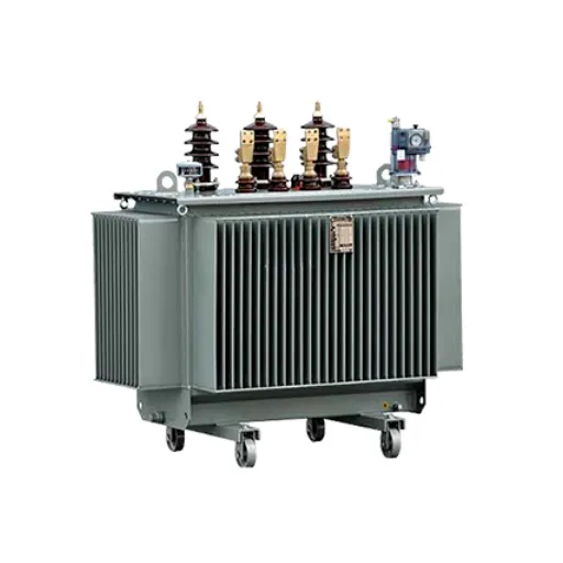
Standardization, in reality, assures that the safety and performance of said apparatus are met, as well as its interoperability. But what relevance from the standards should be understood is the efficient functioning of the specifications and their effects on the quality.
IEC 60076 Series Overview
IEC 60076-1: General Requirements
Rules that are fundamental are founded entirely on the basic features of power transformers, as well as the principles of rating, the application-related tolerances, testing requirements, and particulars to be used by the manufacturer, as well as the user. Generally, all oil immersed power transformers are covered by this founding standard.
IEC 60076-2: Temperature Rise
Defines temperature rises and testing methods to use to verify thermal behavior. The compliance regulates the temperature aspects of transformers during rated load operations.
IEC 60076-3: Insulation Levels and Dielectric Tests
Insulation coordination requirements regarding lightning impulse withstand levels, power frequency dielectric tests, and switching impulse requirements for high-voltage equipment. Standard insulation levels include:
- 12 kV equipment: 75 kV impulse, 28 kV power frequency
- 24 kV equipment: 125 kV impulse, 50 kV power frequency
- 36 kV equipment: 170 kV impulse, 70 kV power frequency
IEC 60076-5: Ability to Withstand Short-Circuit
Withstands the prescribed requirements of short-circuit withstand capability both mechanically and thermally. Compliance must be verified by testing or reliable calculation based on proven design rules.
IEC 60076-7: Loading Guide
Offers a very clear introduction to oil-impregnated power transformers under different ambient temperatures and loads. An operator is allowed to deal with filtration loss-induced aging by determining optimum loading profiles.
IEC 60076-10: Sound Levels
For measuring methods and ensuring typical noise limits. Normal representation transformers produce noise from 50 – 60 dB(A), depending on their capacity, while big power ones have up to 70 to 80 dB(A).
IEC 60076-14: High-Temperature Insulation Materials
Deals with liquid-filled transformers that heat up by using high-temperature insulation systems and insulating liquids of high fire point. Thus, it can go for operation at a higher temperature or safety enhancement resulting from fire through ester fluids.
International Certifications and Approvals
CE Marking (European Economic Area)
CE marking typically requires compliance with the EN 60076 series. With this, CE marking also implies that the products are covered by the Low Voltage Directive (2014/35/EU) and Electromagnetic Compatibility Directive (2014/30/EU).
UL Listing (North America)
UL 1562 applies to the big air-cooled dry-type and oil-immersed power transformers used in the North American market. UL does evaluations and inspects it because this must be done in viewing to become UL certified.
IEEE C57.12.00 and C57.12.90
In the description of IEC 60076, which specifies byte transformation, the IEEE controls are very similar to those of the IEC. Some of the differences are in the methods of testing and the rating conventions. Therefore, North American applications are often equipped with double marks, both according to IEEE and IEC standards for transformers.
KEMA/CESI Third-Party Testing
In connection with it, the external testing by institutions like KEMA or CESI is evidence of a quality in its design and manufacture beyond the self-certification claimed by the producer itself. Built beyond self-certification, weight is given in the decision process of international tender evaluations attributed to such certifications.
Quality Assurance and Factory Testing
Routine Tests (Every Unit)
- Measurement of winding resistance
- Measurement of voltage ratio and verification of vector group
- Measurement of short-circuit impedance and load loss
- Measurement of no-load loss and current
- Applied voltage test (winding to ground)
- Induced voltage withstand test
Type Tests (Design Verification)
- Temperature rise test
- Lightning impulse test
- Switching impulse test (for high-voltage units)
- Short-circuit withstand test
Special Tests (When Specified)
- Partial discharge measurement
- Measurement of zero-sequence impedance
- Measurement of harmonics
- Sound level measurement
Factory acceptance testing provides quality verification before shipment. Witness testing by customer representatives or third-party inspectors adds assurance for critical applications.
Future Trends: Eco-Friendly & Smart Transformers
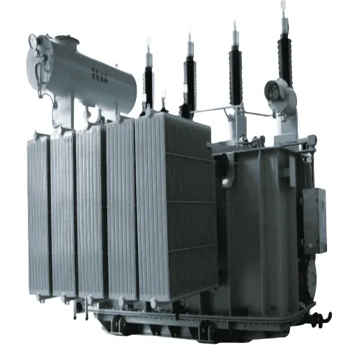
The transformer industry continues evolving toward enhanced environmental performance and digital integration. Understanding emerging technologies enables future-ready specification decisions.
Natural Ester and Synthetic Ester Adoption
Adding Ester-based insulating fluids gains momentum with the environmental requirements as well as fire safety measures. Such regulations and chemical prohibition laws, such as REACH from the European Union, call for a shift to biodegradable material from its petroleum origin.
The esters are able to facilitate designs of transformers, which would need less infrastructure for fire protection, valuable in urban substations and indoor installations. Their initial costs may be higher and very well justify such an investment, also reducing infrastructure and environmental risks.
Ester is found in the transformer-filled design in the capacity range from very low distribution units to MVA transformers exceeding 100 MVA. Necessary compatibility with materials has solved the doubt about gaskets and insulation system reactions to ester fluids.
Digital Monitoring and Predictive Maintenance
Intelligent transformer condition monitoring systems are being introduced, utilizing a range of sensors to obtain a comprehensive assessment of condition requirements, including:
- Monitoring temperature, especially in the location of the most eminent hot spot.
- Detection of DGA of condensed gases with the use of online and manual methods
- Monitoring of bushings for the trend in power factor and capacitance measurements
- Discovering partial discharges that shall detect the test level IA assessment
- Trending on the performance status through measuring the load current and voltage
Aggregated data and cloud-based analysis would allow the storm of predictive maintenance strategies to create a list of optimal resource and timing allocation for maintenance. Machine learning algorithms identify very slight patterns of issues in the making well before any alarms would have been set off by traditional threshold monitoring methods.
These systems support the broader digital substation concept by integrating transformer condition data with switchgear, protection, and control system data forms so that holistic asset management can be made possible. This means considerable savings can be made in preventive and maintenance breakdowns through digital monitoring in the case of big Transformer fleets that air operators manage.
Efficiency Improvements and Sustainability
Amorphous metal core materials reduce no-load losses by 60-70% compared to conventional grain-oriented silicon steel. While higher material costs limit application to specific high-efficiency requirements, improving manufacturing economies continue to expand viable applications.
Optimized winding designs using transposed conductors and improved insulation systems reduce load losses while maintaining reliability. These incremental improvements collectively contribute to transformer efficiency reaching 99% or higher for large power units.
Lifecycle carbon footprint analysis increasingly influences transformer selection. Extended service life, reduced losses, and recyclable materials all contribute to improved environmental profiles that align with corporate sustainability commitments.
Ready to specify oil immersed power transformers for your next project? Request a customized quotation from our engineering team, including detailed specifications, delivery schedules, and lifecycle cost analysis tailored to your application requirements.
Conclusion
The correct selection of oil-filled transformers requires striking an equilibrium between technical specifications, application requirements, and lifecycle economics. Key points in this handbook furnish the foundation for making well-informed decisions:
- Oil-filled technology is the clear advantage in high-end, outdoor, and heavy industrial applications, where thermal advantage and cost efficiency ensure its relative supremacy despite additional infrastructure cost for fire safety and containment of oil.
- The IEC 60076 standards are applied to specify and verify transformer performances. Proper understanding of different cooling methods (ONAN, ONAF, OFAF), temperature ratings and testing requirements ensures the right technical evaluation.
- Esters are biodegradable options that are quite promising with respect to mineral insulation oils in terms of fire safety and the environment, as well as preserving electrical performance, as they vastly extend the application range of oil-type applications to forms that were conventionally the domain of dry-type designs.
- The implemented discipline encompassing routine dissolved-gas analysis and oil quality analysis is the reason why the system could be relied on for its 25 to 40 years of design life; therefore, the opportunity has to conditionally monitor and predict its reparation before it goes down instead of just reactive renewals.
- Today, by implementing real-time monitoring with digitally integrated solutions, a new range of transformer periods has come into practice, and actual digitized changing of the need for midterm conditions is provided. This adds a significant reduction in costs and a major improvement in analytical methods, taking digital real-time monitoring to predictive maintenance of transformers.
Thus, an extensive supported infrastructure investment and the growth trend for electrification have pabulumized great potential for a rise in the global transformer market to USD 137.72 billion by 2032. The fact that technical and supply personnel may be the stakeholders to learn from alternative conditions remained one prerequisite: to avoid the risks associated with project failure or poor operational reliability over the years.
If you are specifying transformers for a utility substation, the plant of an industry, or other renewable energy projects, this handbook will outline the main aspects of the designed equipment so that you can feel more confident in equipment selection. Proven oil-immersed technology, when wed to emerging digital equipment, will position these systems as being core and relevant to existing and future power transmission and distribution infrastructure systems and setups on a global scale.
Please contact Shandong Electric so that our trained engineering team knows about the specific requirements of your transformers. We provide a tailored oil-immersed power transformer solution as per the standard set down in the confines of IEC 60076, together with a comprehensive degree of technical support, from specification through to installation, and all maintenance while in operation over its life cycle.