
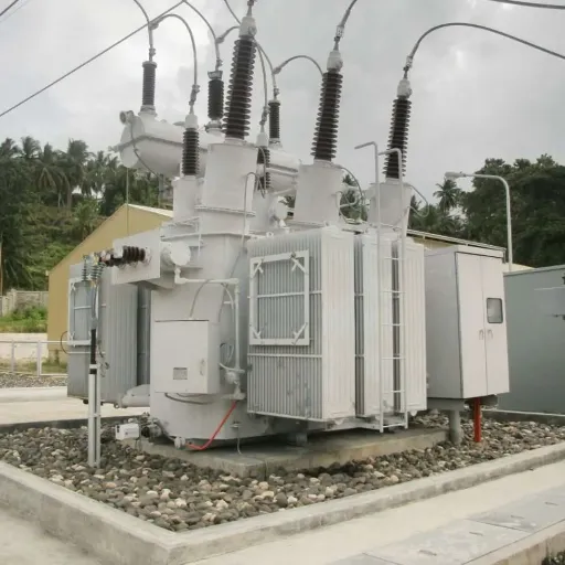
Phase Shifting Transformer Guide: Working Principles, Applications & Selection

Energy does not always go where you want it to go. Energy always goes to where physics allows.
In 2019, a major European utility was in a quandary. They had contracted to buy 800 MW of clean energy from another country. Those electrons usually follow the road of least resistance. This time, however, they veered off course and instead travelled through a completely different path. That power circulated through an inadvertent 400-km loop and got so heavy that it went over domestic power lines and affected stability in three regions. The situation was not so much about capacity or agreements as it was about impedance.
This is why regulating the thrust of phase shift transformers has become the essence of sophisticated power grids. These machines do not just transmit electricity but have a place in determining where it goes.
This guide aims to walk you through everything you need to know about phase shift transformers, their value point as well as how to tell whether your project requires one or not. Whether managing grid interconnections, industrial rectification systems, or evaluating power flow solutions, this article generates the technical grounds for wise engineering decisions.
What you’ll learn:
- The fundamental physics behind phase angle control
- Different PST architectures and their applications
- Real-world sizing and selection methodology
- Standards compliance requirements (IEC, IEEE)
- How PSTs compare to alternative power flow control technologies
What Is a Phase Shifting Transformer?
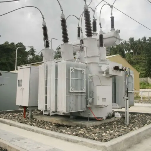
Phase shifting transformers are a special kind of transformer that enable the management of real power transmission among alternating current transmission networks through inducing an adjustable shift in phase angle between voltages at both the input and output ends of the transformer. In contrast to the traditional transformers, which involved changes in the voltage magnitude, Phase Shifting Transformers introduced a gesture of shifting the phase between voltages to send power through one of the parallel transmission lines.
You may have heard these devices referred to as either:
- Phase Angle Regulators (PAR)
- Quadrature-Boost
- Phase Angle Regulating Transformers (PART)
The difference is marked because PSTs are needed for something entirely different from the standard step-up or step-down transformer. The answer again will be asked: how are we going to change the voltage levels? A phase-shifting transformer would answer: How do we control where power flows?
The Power Flow Problem
To understand why PSTs matter, consider the basic equation governing active power flow in AC systems:
P = (V₁ × V₂ / X) × sin(δ)
Where:
- P = Active power flow
- V₁, V₂ = Voltages at sending and receiving ends
- X = Line reactance
- δ = Phase angle difference between the two voltages
The critical insight: power flow depends directly on the phase angle difference δ. By adjusting this angle, you control the magnitude and direction of power flow without changing the transmission line itself.
In interconnected grids, this capability solves three persistent challenges:
- Parallel Path Loading: When multiple transmission paths exist between two points, power naturally favors the lower-impedance route. PSTs force redistribution to prevent overloading shorter lines while underutilizing longer ones.
- Loop Flows: In meshed networks, power can circulate through unintended paths, causing congestion and losses far from the source. PSTs break these loops.
- Contractual Alignment: Power markets schedule flows, but physics determines actual paths. PSTs align physical flows with contractual obligations.
According to industry analysis, the global PST market reached approximately 1.80billionin2024andisprojectedtogrowto1.80billionin2024andisprojectedtogrowto4.50 billion by 2033, representing a compound annual growth rate of 10.2%. This growth reflects increasing grid complexity, renewable energy integration, and cross-border interconnection projects worldwide.
How Phase Shifting Transformers Work
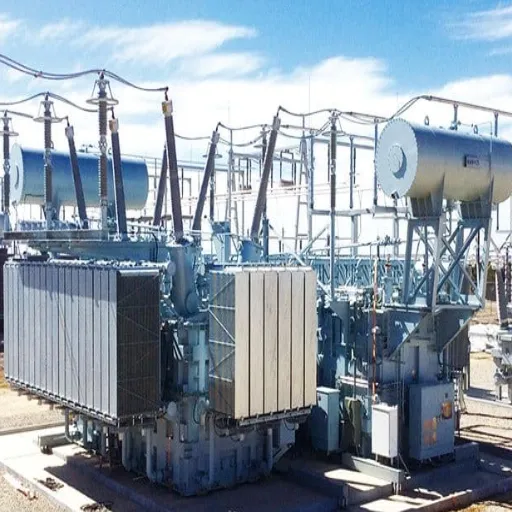
Its working principle is a phased-shifting transformation, affecting the manipulation of the Voltage Phasor. A PST does a 90° rotation for the output Voltage Phasor’s line values by the introduction of an orthogonal voltage component over the line voltage to vary the phase relation, which would approximately remain the same as its magnitude.
The Quadrature Voltage Concept
We can look at the line voltage as a straight line that points towards the horizontal axis. The line marked by a PST is nothing but the second voltage vector lying at 90 degrees and perpendicular to this line voltage. And then if vectors are correctly added, these lines transform into rotational 90° apart around the same length.
This perpendicular voltage is what they call the quadrature voltage. The variation in phase between this kind of transformer can be controlled with tap changers.
Two-Unit Architecture
In the majority of cases, large PSTs follow a two-transformer configuration employing shunt and series units.
Exciter Transformer (Shunt Unit)
Incoming quadrature voltage is employed, and the various functions are associated with the following points:
Parallel connect across the three-phase line. The Shunt unit provides:
- Tapping excitation from the line to energize the system
- Producing the quadrature voltage shift for 90 degrees from the line voltage
- Magnitude control through the action of an on-load tap changer (OLTC)
In creating a steering force, the shunt essentially redirects power flow.
Booster Transformer (Series Unit)
The series unit connects with the transmission line conductors in series. Major functions of the series unit are:
- Taking in quadrature voltage from the shunt unit
- Vectorizing this voltage, injecting it in the line
- Final change of output phase angle with respect to input
Probably, a steering force would help you alter the direction of power flow.
Operating Modes
PSTs commonly operate in two ways.
Boost mode: Required to increase the phase change between the input and output voltage. It raises the effective angle difference δ, which increases the real power delivered to the load. Normally, grid operators utilize the boost mode when they finally need to get the maximum capability of power capacity through a particular transmission corridor.
Buck Mode: PST drops the level of phase shifting and hence of the effective δ. This leads to a low real power flow toward the load. Buck mode transfers power from the original mingled route to another path that requires power over interconnected lines.
The transition between operating points is through on-load tap-change (OLTC) devices employing special transition resistors, which make it possible for taps to be changed during loading without interrupting power transmission, with normal phase shift adjustments being carried out in 2 to 5 s per tap step.
Different varieties vital in providing desirable performance in the Refraction Phase Shift Transformer include modern designs, which can achieve the phase shift range of ±10° to ±20° typical for symmetrical types, while some peculiar designs will produce a performance up to ±40° or more for asymmetrical configurations.
Types of Phase Shifting Transformers
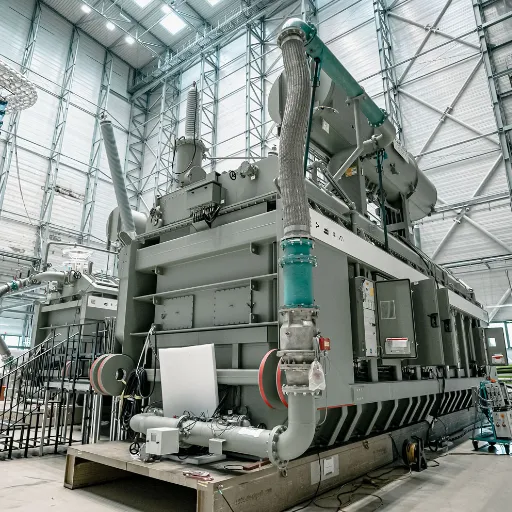
Phase shifting transformers vary in construction, characteristics, and application scale. Understanding these differences helps specify the right solution for your project.
By Construction Architecture
Direct PST (Single Integrated Unit)
Direct PSTs integrate the exciter and booster functions within a single transformer structure. The windings interconnect internally to create the required phase shift.
Advantages:
- More compact footprint
- Lower installation complexity
- Reduced interconnection cabling
- Generally lower cost for smaller ratings
Best Applications:
- Lower MVA ratings (typically under 300 MVA)
- Smaller phase shift requirements
- Space-constrained installations
- Distribution-level applications
Indirect PST (Separate Exciter and Booster)
Indirect PSTs use two physically distinct transformers connected through cables or buswork. The exciter and booster units occupy separate tanks.
Advantages:
- Higher power ratings achievable
- More flexible for complex installations
- Easier maintenance access
- Better heat dissipation for large units
Best Applications:
- High-voltage transmission (400 kV and above)
- Large phase shift requirements
- Ratings exceeding 500 MVA
- Critical infrastructure requiring redundancy
By Phase Characteristics
Symmetrical PST
Symmetrical phase shifting transformers change only the phase angle while maintaining constant voltage magnitude between input and output.
Characteristics:
- Input and output voltage magnitudes remain equal
- Phase angle changes in a positive or negative direction
- Simpler design and operation
- Most common for transmission applications
Typical Phase Range: ±10° to ±20°
Asymmetrical PST
Asymmetrical PSTs change both phase angle and voltage magnitude simultaneously.
Characteristics:
- Provides voltage regulation in addition to phase control
- More complex design with additional tap windings
- Greater operational flexibility
- Higher cost and complexity
Typical Phase Range: ±20° to ±40° or more
By Application Scale
Transmission-Level PST
These are large power system devices designed for grid-scale applications.
Typical Specifications:
- Power ratings: 400 MVA to 1600+ MVA
- Voltage levels: 220 kV through 550 kV
- Phase displacement: ±10° to ±20°
- Applications: Interconnection control, load sharing, congestion management
Industrial rectifier transformers are characterized as belonging to another closely related group, where the principles of phase modulation are used not for the purpose of controlling power flow but for attenuation of harmonics
Typical specifications:
- Power ratings: 1 MVA to 100 MVA
- Voltage levels: 0.4 kV to 35 kV
- Specific fixed phase shifts at secondary windings: 15°, 20°, 30°
- Applications: Multipulse rectification (12pulse, 18pulse, 24pulse)
These transformers create phase-displaced secondary windings, such that when rectified and then combined, they will cancel specific harmonic orders, usually 5th and 7th harmonics, as one can observe in the 12-pulse system. Thus, this enhances the power quality and decreases the total harmonic distortions (THD) in an industrial establishment.
Comparison Summary
| Type | Best For | Phase Range | Complexity | Relative Cost |
|---|---|---|---|---|
| Direct PST | Compact installations, <300 MVA | ±10° to ±20° | Lower | Lower |
| Indirect PST | Large systems, >500 MVA | ±10° to ±40° | Higher | Higher |
| Symmetrical | Standard grid applications | ±10° to ±20° | Standard | Standard |
| Asymmetrical | Complex flow control needs | ±20° to ±40° | Higher | Higher |
| Rectifier Type | Industrial harmonic mitigation | Fixed (15°, 20°, 30°) | Medium | Medium |
Key Applications of Phase Shifting Transformers
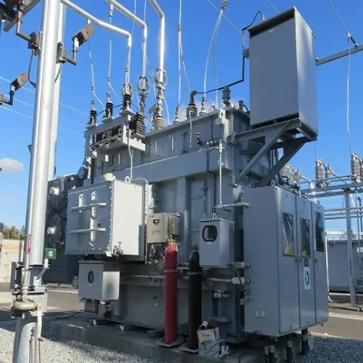
Phase-shifting transformers have very significant functionality in transmission system networks, industrial plants, and the like, in emerging renewable energy systems. The best possible explanation of the ways phase shifting transformers contribute value is through understanding the applications in which they can help.
Grid Load Balancing as well as Congestion Management
In meshed transmission networks with parallel paths, phase-shifting transformers prevent the overloading of the routes with a low impedance, which, in turn, maximizes the utilization of available capacity.
Real-World Scenario:
Consider the regional grid interconnected with two transmission corridors linking Area A and Area B. Corridor 1 is a 150 km-400 kV line with X₁ reactance, and Corridor 2 is a 300 km-X₂ = 2X₁ reactance. Since the How systems are established, there is about 92 to 8 power flow towards Corridor 1, and Corridor 1 can take no more than 33% load with the given capacities.
When the peak demand hits, corridors will be approaching their thermal limits, making the operating conditions interesting: there will be unused capacity in the parallel corridor 2; however, the flow distribution will inevitably be as prescribed by physics. A PST could be installed at the Corridor 1 substation, generating a phase shift that leads to a flow of 30-50% to the parallel Corridor 2. This shift loads balance and prevents congestion.
This system will ensure that grids evolve well. According to information from the transmission system operator, PSTs, positioned suitably, are able to divert power flow between parallel paths, massively increasing power carrying capacity by 70% without additional lines.
Cross-Border Power Control
International electricity markets depend on physical power flows matching contracted schedules. PSTs installed at border interconnections ensure this alignment.
The Challenge:
When Country A contracts to import 500 MW from Country B, market systems record the transaction. But the actual electrons may flow through Country C if that path offers lower impedance. This creates:
- Uncompensated loop flows through transit countries
- Congestion on unintended transmission paths
- Market settlement disputes
- System stability risks
The Solution:
PSTs at strategic interconnection points allow transmission system operators to:
- Align physical flows with market schedules
- Prevent unscheduled transit flows
- Maintain contractual integrity
- Protect domestic grid stability
The European Union has installed numerous PSTs at internal borders specifically to manage these challenges as cross-border electricity trading has increased.
Renewable Energy Integration
The above passage used information that revealed that variable renewable wind and solar generation have led to many more changes to power flows, in a way that static transmission infrastructure cannot handle well.
Applications:
Wind Farm Connections: Many times, big wind farms, such as offshore facilities for wind power, are connected at far-away points to shore to which they come. Periods of very high generation are managed by PSTs, in this fashion, preventing a subsequently reversed flow of power over domestic lines.
Solar PV Integration: Distributed solar power results in two-way flows of power fed to and coming from distribution substations. PSTs positioned in upstream transmission lines manage these fluctuations without an upgrade in infrastructure.
Adjusting Grid Stability: Fluctuations in renewable output of any sort would bring about a situation of serious changes in the distribution of power. Automated, instantaneous action is taken in very few seconds when PSTs can be brought under control within an operational environment that remains stable.
The renewable energy sector has been one of the fastest-growing drivers for PST installations. Market research has shown that between 7.5-10% annually, demand growth is predicted in the high renewable penetration regions.
Industrial Multi-Pulse Rectification
Beyond transmission applications, phase-shifting principles enable cleaner power conversion in industrial environments.
12-Pulse Rectifier Systems:
A phase-shifting rectifier transformer provides two secondary windings with a 30° phase displacement. When each secondary feeds a six-pulse rectifier bridge, and the DC outputs combine, the harmonic content changes significantly:
- 6-pulse systems: Generate significant 5th and 7th harmonics (THD ~30%)
- 12-pulse systems: Cancel 5th and 7th harmonics through phase opposition, reducing THD to under 10%
This harmonic reduction:
- Improves power quality for sensitive equipment
- Reduces heating in cables and transformers
- Avoids utility penalties for excessive harmonic injection
- Extends equipment lifespan
Industries Using Phase-Shifting Rectifier Transformers:
- Metallurgical: Aluminum smelting, copper refining, steel production
- Chemical: Chlor-alkali electrolysis, hydrogen generation
- Transportation: Traction power supplies, marine systems
- Data Centers: Large UPS installations requiring clean power
Phase Shifting Transformer Selection Guide
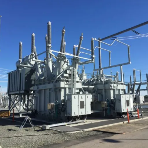
Specifying a phase shifting transformer requires a systematic analysis of electrical requirements, system constraints, and operational parameters. This section provides a methodology for proper sizing and selection.
Key Specifications to Define
Voltage and MVA Rating
The PST must accommodate:
- System voltage level: Rated for the nominal transmission voltage (e.g., 220 kV, 400 kV)
- Maximum continuous current: Based on maximum anticipated power flow
- Overload capability: Short-term ratings for emergency conditions (typically 1.2-1.5x continuous for a limited duration)
For a transmission line rated at 2,000 MVA, the PST typically requires a similar rating capability to handle full line capacity in either direction.
Phase Shift Range
Determine required phase shift based on power flow analysis:
- Calculate the maximum power transfer needed in each direction
- Model system impedance and existing phase angles
- Determine the phase shift required to achieve target flows
- Add margin (typically 20-30%) for future system changes
Typical Ranges:
- Standard transmission applications: ±15° to ±20°
- Complex grid configurations: ±25° to ±35°
- Special applications: up to ±40° or more
Tap Changer Specifications
The on-load tap changer determines operational flexibility:
- Number of steps: More steps provide finer control (typical: 17-33 steps)
- Step size: Smaller steps mean more precise flow control (typical: 0.5° to 2° per step)
- Switching time: Faster response for dynamic conditions (typical: 2-5 seconds per step)
- Transition type: Resistor or reactor type based on switching current magnitude
Cooling Method
Cooling selection affects footprint, maintenance, and reliability:
Oil-Immersed (ONAN/ONAF/OFAF):
- Higher power ratings achievable
- Proven long-term reliability
- Requires oil containment and fire protection
- Maintenance includes oil testing and filtration
Dry Type:
- Lower fire risk
- Reduced maintenance
- Smaller ratings typically (under 50 MVA for PST applications)
- Higher capital cost per MVA
Sizing Methodology
Step 1: Power Flow Analysis
Perform load flow studies for:
- Normal operating conditions
- Peak demand scenarios
- Contingency conditions (N-1 analysis)
- Future system expansions (5-10 year horizon)
Identify:
- Maximum loading on constrained lines
- Required power flow redistribution
- Phase angles under various conditions
Step 2: PST Impact Modeling
Model the PST in your power system simulation:
- Determine required phase shift range
- Calculate expected power flow changes
- Verify the relief of constraint conditions
- Check for unintended effects on other lines
Step 3: Specification Development
Based on the analysis, specify:
- Rated power (MVA)
- Voltage levels (primary and secondary)
- Phase shift range and steps
- Tap changer requirements
- Cooling method
- Impedance characteristics
- Short-circuit withstand capability
Step 4: Future Expansion Planning
Consider:
- Expected load growth
- Planned generation additions
- Transmission system expansions
- Potential market changes
Size the PST with a 20-30% margin above immediate requirements to accommodate future needs without replacement.
Standards and Compliance
International and regional standards are abided by phase-shifting transformers:
IEC Standards
- IEC 62032: Guideline for the Application of Phaseshift Transformers and Embedded IEDs
- IEC 60137: Insulated bushings above 1,000 V for alternating voltages
- IEC 60076 series: General standards regarding power transformers, detailing aspects of loss testing, and temperature increase
IEEE Standards
- IEEE C57.135: IEEE Standard for Phase-Shifting Transformers Applied in Power Systems
- IEEE C57.12. 00: General requirements for liquid-immersed transformers
- IEEE C57.131: Tap Changers Standards
Regional Requirements
- Europe: ENTSO-E network codes, the national grid code
- North America: NERC standards and regional transmission organization (RTO) requirements
- Asia-Pacific: Country-specific grid codes and utility standards
It is indicated that when planning the project, all the standards that should be addressed should be determined immediately. The requirements for testing documentation and verification of compliance can vary greatly between different jurisdictions.
Installation and Maintenance Considerations
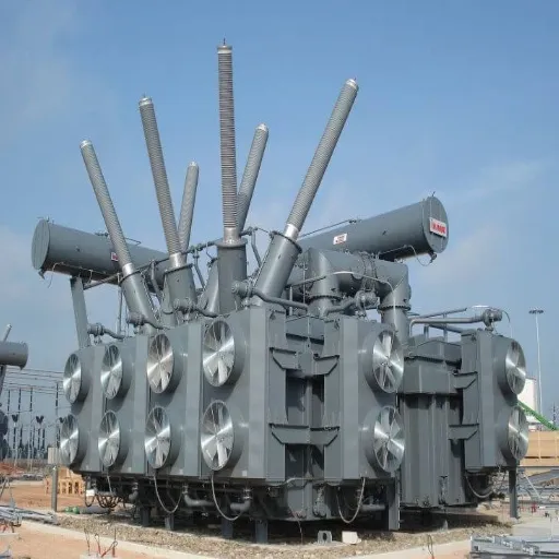
Proper installation and maintenance ensure reliable PST operation over the transformer lifecycle, which typically spans 30-40 years for transmission-level units.
Installation Requirements
Site Preparation
Foundation:
- Design for total weight including oil (may exceed 500 tons for large units)
- Allow for jacking points for future maintenance
- Provide containment for oil spill protection
- Consider seismic requirements for the region
Clearance:
- Adequate spacing for cooling airflow (oil-immersed units)
- Access for inspection and maintenance
- Clearance for tap changer mechanism servicing
- Safe working distances for live components
Protection Coordination
Integrate PST protection with system protection schemes:
- Differential protection: Primary transformer fault detection
- Buchholz relay: Gas detection for internal faults (oil-filled units)
- Temperature monitoring: Winding and oil temperature alarms and trips
- Pressure relief: Rapid pressure rise protection
- Tap changer monitoring: Step position verification, motor overload protection
Coordinate protection settings with:
- Adjacent line protection
- Remote end protection
- System stability requirements
Control System Integration
Modern PSTs include sophisticated control systems:
- Local control panel: Manual operation, status indication, alarms
- Remote terminal unit (RTU): SCADA integration for remote monitoring and control
- Automatic control: Response to system conditions (voltage, current, power flow)
- Communications: IEC 61850, DNP3, or proprietary protocols for integration
Plan communication pathways and control center integration during the design phase.
Maintenance Requirements
Routine Inspections
Monthly:
- Visual inspection for oil leaks (oil-filled units)
- Review of temperature readings and alarm status
- Check of control system status indicators
Quarterly:
- Inspection of cooling systems (fans, pumps)
- Verification of control system functions
- Review of operating history and tap change counts
Annual Maintenance
Tap Changer Servicing:
The tap changer requires the most intensive maintenance:
- Inspection of contacts and transition resistors
- Oil replacement or filtration (oil-type tap changers)
- Drive mechanism lubrication and adjustment
- Contact wear measurement and replacement as needed
Oil Testing (Oil-Filled Units):
- Dissolved gas analysis (DGA) for fault detection
- Moisture content measurement
- Dielectric strength testing
- Acid number and interfacial tension tests
Major Maintenance
Every 5-10 years, schedule comprehensive maintenance:
- Complete tap changer overhaul
- Bushing inspection and power factor testing
- Winding resistance measurements
- Turn ratio verification at all tap positions
- Insulation power factor testing
- Thermal scanning for hot spots
Monitoring and Diagnostics
Modern PSTs benefit from continuous monitoring:
Online Monitoring Systems:
- DGA monitoring (real-time fault gas detection)
- Partial discharge detection
- Winding hot spot temperature calculation
- Tap changer operation monitoring
Diagnostic Testing:
- Frequency response analysis (FRA) for winding deformation detection
- Sweep frequency response analysis for bushing condition assessment
- Thermographic surveys for connection integrity
Implement a condition-based maintenance approach using monitoring data to optimize maintenance intervals and predict potential failures before they occur.
Advantages and Limitations
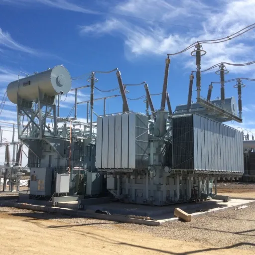
Understanding both the capabilities and constraints of phase shifting transformers helps determine when they represent the optimal solution.
Advantages
Passive Technology
PSTs contain no power electronic components. They rely entirely on electromagnetic principles and mechanical tap changers. This provides:
- High reliability: No semiconductor failure modes
- Robust operation: Tolerates harsh environmental conditions
- Proven technology: Decades of operational experience
- Simple protection: Conventional transformer protection schemes apply
Cost-Effectiveness for Large Ratings
For high-power transmission applications (100+ MVA), PSTs offer favorable economics:
- Lower capital cost than FACTS devices for equivalent power ratings
- Lower losses than power electronic alternatives
- Long service life (30-40 years typical)
- Proven manufacturing base with multiple qualified suppliers
Grid-Forming Capability
Unlike some power electronic solutions, PSTs:
- Provide inherent short-circuit capacity contribution
- Maintain voltage support during disturbances
- Do not require external power for operation
- Continue operating during system disturbances that might trip electronic devices
Operational Simplicity
Once installed and configured, PSTs require:
- Minimal operator intervention
- Straightforward control schemes
- Conventional maintenance procedures familiar to utility staff
- No specialized software or firmware management
Limitations
Slow Response Time
Mechanical tap changers limit response speed:
- Step time: 2-5 seconds per tap change
- Full range traversal: 30-90 seconds typical
- Inability to respond to rapid transients or sub-cycle disturbances
For applications requiring millisecond response (voltage stability, power quality), FACTS devices or power electronic solutions may be more appropriate.
Maintenance Requirements
The mechanical tap changer requires regular maintenance:
- Contact wear: Mechanical switching causes gradual contact degradation
- Oil maintenance: Oil-filled tap changers require periodic oil service
- Mechanical adjustments: Drive mechanisms need periodic calibration
- Availability impact: Maintenance requires taking the PST out of service
Limited to Phase Angle Control
PSTs manipulate only the phase angle relationship. They cannot:
- Provide reactive power compensation
- Inject or absorb vars for voltage control
- Act as harmonic filters
- Provide dynamic voltage support
Applications requiring these capabilities need complementary devices (STATCOMs, SVCs, harmonic filters) in addition to or instead of PSTs.
Physical Size and Weight
Large transmission PSTs are substantial installations:
- Weight: 200-600+ tons for major units
- Footprint: Large foundation requirements
- Transport: Special permits and routing for delivery
- Oil volume: 50,000-150,000 liters for oil-filled units (with associated spill containment requirements)
These factors can limit application in space-constrained substations or environmentally sensitive areas.
Comparison with Alternative Technologies
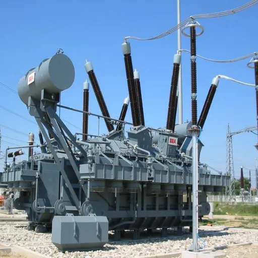
There are different available solutions for managing the electricity flow, and they are typically categorized by the technology used in each instance. Understand that there are alternatives associated with power flow management.
PST vs. FACTS Devices
Flexible AC Transmission Systems (FACTS) use power electronics to provide dynamic control of transmission parameters.
Static VAR Compensator (SVC)
Function: Compensation of reactive power for faster control of voltage
Comparison:
- SVCs are meant for the voltage control, while PSTs are for controlling the flow of power.
- SVC control is in milliseconds, while that of PST is in seconds.
- Power electronics are always utilized on the SVC, while PSTs are always passive.
- AC filters the harmonics of the SVC; PT does not.
Selecting SVC: Voltage Instability Problems, Rapidly Required Reactive Power, Fluctuation Compensation
Selecting PST: Active Power Flow Control, Steady-State Loading Management
Static Synchronous Compensator (STATCOM)
Function: Dynamic reactive power control derived voltage source converter
Comparative:
- STATCOMs are quicker than the SVCs (with sub-cycle response
- In return, a higher capital cost for equivalent ratings of the PSTs
- A complex control system and costly maintenance are required.
- Much smaller than the PSTs
When to Choose STATCOM: dynamic voltage support, weak grid connections, and networks that integrate renewable energy with voltage challenges.
When to Choose PST: projects that focus on managing active power.
Unified Power Flow Controller (UPFC)
Function: It combines shunt and series compensation to control power flow and voltage simultaneously
Comparison:
- UPFCs manage voltage, impedance, and phase angle simultaneously
- However, the most powerful FACTS tool at present has indeed become more advanced but is also, therefore, more costly.
- Power electronics has a challenging complexity that demands specialized expertise
When UPFC could be best used: Complex issues and technical challenges that are linked to multiple operating modes and associated control challenges
When PST is better: Low-cost and simpler active power flow control
PST vs. HVDC
High Voltage Direct Current (HVDC) transmission provides an alternative for power flow control, particularly over long distances or between asynchronous grids.
Technical Comparison
| Factor | PST | HVDC |
|---|---|---|
| Power flow control | Phase angle manipulation | Direct current conversion |
| Distance capability | Best for <300 km | Economical for >500 km |
| Asynchronous connection | No | Yes (key advantage) |
| Cost | Lower for short distances | Lower for long distances |
| Losses | ~0.5-1% | ~3-5% (converter stations) |
| Footprint | Large transformer | Converter stations + cables/lines |
| Complexity | Moderate | High |
Application Guidelines
Choose PST When:
- Connecting synchronous AC systems
- Distance is relatively short (<300 km)
- Cost minimization is important
- Simple operation and maintenance are priorities
Choose HVDC When:
- Connecting asynchronous grids (different frequencies)
- Undersea or underground transmission required
- Very long distances (>500 km)
- Precise power control independent of AC system conditions is needed
Integrated Solutions
Modern grid challenges often require integrated approaches:
PST + STATCOM: Combines active power flow control with dynamic voltage support
PST + Series Compensation: Adds impedance control to phase angle control
PST + Energy Storage: Combines steady-state flow control with energy time-shifting
These hybrid solutions address complex system requirements but increase cost and complexity. A thorough system study determines whether the incremental benefits justify the additional investment.
Conclusion
Phase shifting transformers solve a specific but critical problem in modern power systems: controlling where active power flows in AC networks. By introducing a controllable phase angle shift between source and load, PSTs redirect power from overloaded paths to underutilized capacity, align physical flows with market schedules, and enable integration of variable renewable generation.
Key Takeaways
- Phase shifters impose the phase angle rather than the voltage magnitude. Power transfer active control could be allowed without retouching the transmission infrastructure of the line, which is actually entirely different from the way of traditional character power flow control.
- By injecting in quadrature voltage, phase rotation is obtained while maintaining the same voltage magnitude, allowing for a very precise distribution of power between parallel paths.
- Interrelationships emerge, whether in transmission or industrial arenas. Grid operators use PSTs to balance loads and manage congestion, while in power systems industries, phase-shifting rectifier transformers help in managing harmonics in multipulse systems.
- Right-sizing demands proper system analysis. A load-flow study is mandatory for any specification of PST, as are future-planning expansion as well as the definition of phases shifted and tap changer specifications.
- Ensures adherence to standards. IEC 62032 and IEEE C57.135 together would form the PST’s technical auspices in framing, testing, and application.
- Selecting between technologies involves a lot of trade-offs. In steady-state power flow control, phase-shifting transformers offer proven reliability and cost savings but cannot compete in response effects with FACTS devices or the flexibility of high-voltage direct current for asynchronous interconnection.
When to Specify a Phase Shifting Transformer
Consider a PST when your project involves:
- Parallel transmission paths with uneven loading
- Cross-border interconnections requiring flow control
- Integration of renewable generation is causing variable flow patterns
- Loop flows or unscheduled power flows
- Need for cost-effective power flow control without power electronics complexity
Future Outlook
The global market for phase-shift transformer is expected that the growth rate would achieve approximately 10.2% within 2033 for reasons which give rise to requirements about modernizing grids, expanding using renewable energies, and electricity trade which is booming these days across the globe. Due to dynamic and increasingly complex grid configurations, there would be an increased significance of controlling active power flows.
A good tool for engineers and system planners in optimizing transmission infrastructure will be to understand the technology of the phase-shifting transformers and to manage the constraints and ensure the secure delivery of power in a changing energy scenario.
Ready to explore phase-shifting transformer solutions for your project? Our engineering team can help analyze your system requirements, specify the appropriate PST configuration, and deliver a solution optimized for your application. Contact our technical specialists for a consultation.