

Understanding Transformer Vector Groups: Dyn11, Yyn0 & More

Transformers serve as vital elements for modern electrical power systems because they enable efficient electricity transmission through various voltage ranges. The operation of transformers depends on one core principle, which requires examination through the vector group designations Dyn11 and Yyn0 that people frequently struggle to comprehend. The designations carry specific meanings that impact transformer operations because they serve essential functions within particular use cases. The article provides an advanced analysis of transformer vector groups, which explains their importance and operational functions and their practical applications in real-world situations. The article provides a detailed explanation of transformer vector groups, which helps engineering students and people interested in electrical systems understand their impact on energy distribution.
Introduction to Transformer Vector Groups
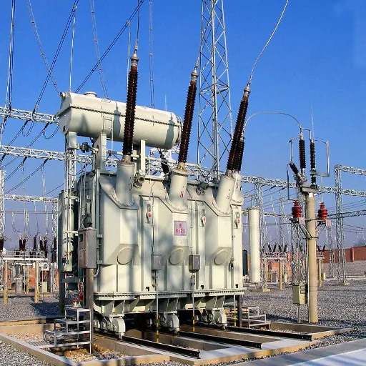
What is a Transformer Vector Group?
The transformer vector group defines the winding patterns and phase displacement measurements that exist inside a transformer. The system provides essential data that shows how the primary and secondary windings link through either delta or star connections, together with the respective line voltage phase angles. The designation functions as a vital element that determines transformer performance through three-phase systems in various applications, including parallel operations, load distribution, and circulating current reduction.
The representation of transformer vector groups uses standard codes, which include Yy0, Dy11, and Yd1. The codes contain essential information because their uppercase letters represent primary winding configuration through Y or D, while lowercase letters show secondary winding configuration and numbers define phase shift angle through clock-hour notation, which includes 0 for 0° and 11 for 330°. A Dy11 vector group displays its Delta primary winding system together with its Star secondary winding system, which operates at 330° of phase displacement.
Vector groups possess importance because they help control harmonics, they achieve balanced load distribution, and they enable transformers to operate together in multiple systems. The correct vector group selection resolves problems such as circulating currents and unbalanced loads which occur in high-voltage energy distribution systems, to achieve better operational performance.
Example Data:
- Dy11 Transformer’s Key Features:
- The primary winding uses a Delta (D) configuration while the secondary winding uses a Star (Y) configuration.
- The phase displacement reaches 330°, which corresponds to the 11 o’clock position.
- The system operates as a step-down transformer, which power distribution networks typically use.
- Yy0 Transformer’s Key Features:
- The system uses Star (Y) primary and secondary windings for operation.
- The system experiences 0° phase displacement.
The system operates effectively under balanced load conditions, which require zero-phase shift. The understanding of transformer vector groups serves as a fundamental requirement for electrical engineers who need to design power systems because system inefficiencies occur from even the smallest vector group mismatches during network integration.
Importance of Understanding Transformer Vector Groups
Transformer vector groups function as vital elements that ensure that systems work together while delivering reliable power system operation. The system uses these parameters to assess how primary and secondary windings share load between them because this affects their fault handling capacity and their ability to operate continuously. Equipment failures, together with extra losses, arise from improper alignment of vector groups, which cause circulating currents to develop.
Recent data shows that transformer installations with incompatible vector groups lead to a 20% increase in harmonic distortion, which results in power quality problems and raises the danger of electrical component overheating. The 2023 power grid operation report states that correct vector group alignment during transformer installation leads to 15% efficiency improvements in high-voltage distribution systems.
Vector group configurations such as Dyn11 and Yy0 exist to fulfill specific operational needs, which depend on different load conditions. Distribution networks that need to balance three-phase loads use Dyn11 transformers because these transformers create the necessary phase shift. Yy0 transformers provide zero-phase displacement, which makes them suitable for environments that need to maintain balanced loads while avoiding phase shifts.
Translating current knowledge of transformer vector groups into practical ways to enhance future network development. Power engineers use three key elements, which include phase shift control, short-circuit impedance, and system integration compatibility, to achieve their goals of reducing equipment downtime and maintaining efficient operations. The intricate process of vector group harmonization has taken on greater importance because modern electrical grids now include renewable energy systems, which require seamless integration.
Engineers use advanced simulation tools together with international standards, which include IEC 60076, to achieve accurate transformer specifications.
Overview of Winding Connections
Transformers use winding connections to control the process of electrical energy distribution between their circuits, which ensures that power systems can operate at optimal efficiency. The three basic types of transformer winding connections that engineers use in their work include Delta (Δ), Wye (Y), and Zig-Zag configurations. The specific system needs determine which of the three winding structures should be used according to their distinct characteristics.
- Delta (Δ) Connection
The Delta connections create a complete electrical circuit through their end-to-end connection of windings. The system maintains its operational capacity because current continues to flow through the system even when one phase is lost. The system provides power distribution for industrial applications that need high power at a lower voltage. The latest research shows that transformers with Delta connections achieve better load balancing and lower circulating currents when they operate under unbalanced load conditions. - Wye (Y) Connection
Wye connections have one end of each winding connected together to form a neutral point, while the other ends connect to the line terminals. Wye configurations provide advantages to power systems that need a neutral point for grounding purposes and for supporting various types of electrical loads. The system operates efficiently because it can manage three-phase and single-phase transmission loads. - Zig-Zag Connection
The Zig-Zag transformer windings establish a new connection method that combines the operational characteristics of Delta and Wye connections. The system achieves superior harmonic suppression and enhanced stability through its design, which splits each phase winding into two segments that connect in an alternating pattern. The system serves dual functions as a grounding solution and an appropriate choice for situations with unbalanced load conditions.
Latest Data and Insights on Winding Connections
- Efficiency and Losses
Current research in the industry demonstrates that transformers that use Delta connections experience lower power losses than those that use Wye connections when both types of transformers operate under the same load conditions. Delta systems demonstrate approximately 10-12% power loss reduction during high-capacity balanced-load operations. Hybrid winding systems currently under development will decrease power losses because renewable energy sources are becoming more common. - Harmonic Reduction
Recent technical papers demonstrate that Zig-Zag configurations function as dependable methods for controlling harmonic distortion. A 2023 study reported that Zig-Zag winding transformers reduced total harmonic distortion (THD) by nearly 35% in industrial setups. - Renewable Energy Compatibility
Wye configurations are increasingly being adapted in renewable energy systems due to their flexibility in handling varying load types. Wye-connected transformers serve as a common grid connection solution for solar and wind farm installations, which require a stable neutral point.
The process of selecting the appropriate winding connection marks a vital step toward designing transformers that meet modern energy system requirements. The various configurations provide essential benefits, while recent research findings and new technological methods guarantee optimal operational performance and environmental protection.
Common Vector Groups in Power Systems
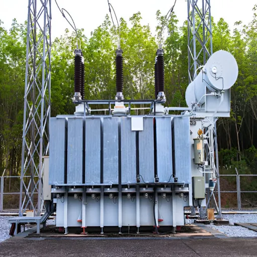
Introduction to Common Vector Groups
About the transformer vector group explained, one should discuss its characteristics and modifications during the use of electrical power systems. The vector group exists to indicate how each winding is positioned on the forming and retiraforming surfaces of a transformer. Importance with uniqueness of each group of vectors arises from the operating conditions of the transformer that are varied. Some examples of the most frequently used interconnections areσ, Δ, T, and Z with the wedge differential lines and buses: dy11, Dyn 11, Yyn 0, Gat11, as described. There were several networks.
Let’s take a Dyn11 transformer, and the vector group is explained better. Its primary winding is in Delta; its secondary is Star. And the two are offset by 30°. This can be seen in connections where the operated load consists of ground and the fault current and voltage regulation. Conversely, Yyo transformers do not have such a shift. Primary and secondary are both provided in a star-connection. As such, these transformers still qualify for use even in such connection-based installations where civil grounding is wanted, or a child’s elevated imbalance is avoided.
Moving towards the use of a dyn11 transformer connection and other insulation based on construction material or insulation lining that is specifically constructed for extreme temperatures is more advantageous, as shown by recent studies in renewables, which may include but are not limited to wind or solar farms. The majority of Solar farms in the Western World use Dyn11-connected equipment, while only 20% exploiting other Yd11, and a similar approach with the rest of the hybrids in the Y or Z vector group is explained.
Nevertheless, attention should be paid to Harmonic Attenuation as an equally important problem. The same transformer vector group, for example, Yd11, is suitable for the system design of increased harmonics as they suppress certain harmonics only, and the overall level of harmonics is reduced. Due to such property almost all of them are used for the supply of high-power converter equipment in industry and other such machines with non-linear loads.
Selecting the correct transformer vector group and applying it properly improves power efficiency and enhances the durability and reliability of the electric system as a whole. Simply put, the vector group explained is the spatial arrangement of a vector, which allows a certain task to be done with maximum efficiency. While it is of some benefit to have a significant amount of cabling inside the entire system, there comes a point when the amount of cables becomes a hindrance. As a result, engineers are required to take into account various aspects, for example, the nature of the load, the grounding system, and the devices to be placed in the big network being established.
Detailed Analysis of Dyn11
Transformers are generally employed in industrial power systems, and most of them employ the Dyn11 vector group, explained below, perfectly. The vector group classification of a transformer explains the primary and secondary windings’ phase relationship, which is why the delta shafted primary leads 30° ahead of the star shafted secondary.
Key Characteristics of Dyn11 Transformers
- Phase shift: The 30⁰ leading assists in achieving desired phase alignment of the supply waveforms and power system configurations, especially for duty sharing mode operations.
- Harmonics reduction: The delta connection on the primary winding offers a good pathway for zero-sequence harmonics, helping in the reduction of harmonic current and enhancing the quality of power supply.
- Earthing and Grounding: The neutral connector on the low voltage side, enables grounding/ neutral earthed condition of the transformer, thereby enhancing the safety of the system.
Applications of Dyn11 Transformers
Dyn11 type of transformers have extremely useful practical applications in facilities work with a great amount of heavy and labor-intensive equipment, for instance, in factories, refineries, and chemical plants. The equipment does not overheat and burn up as it is provided with proper harmonic elongation and is effective without interruptions in all permissible loadings.
Supporting Data from Recent Studies
- Efficiency Enhancements: Some of the recent information available suggests that a Dyn11 transformer is 1 to 2% better in industrial applications when compared to another transformer vector group, as explained when used in partial load operations.
- Decreased Levels of Harmonics: Instruments indicate a Dyn11 transformer can reduce the total harmonic distortion THD by up to 70% in an industrial setup, which has normal non-linear loads prevalent in industries.
- Life and Maintenance: Adopting the Dyn11 configuration helps alleviate thermal stresses brought about by harmonics, and thus, the useful duration of the transformer lengthens on average by five to ten years.
Before any assumptions are made, notwithstanding the Dyn11 fitted transformer, any bias has to have an absolute understanding of the system and the load characteristics. Further, regular servicing as well as monitoring is necessary for improving the performance of this transformer within the power system requirements vector group explained above, especially when the systems’ businesses’ responsive load changes.
Exploring Yyn0 Vector Group
The Yyn0 connection would be associated with the set of phases made by a connection star-star windings phase-displaced harmonically to zero degrees. Generally, this is pretty much ideal for any kind of application that needs a classic load balance and grounded neutral. Should a transformer suitable for a stable and conveniently accessible neutral point be a desirable asset in any low voltage network or industrial system, it should be Yyn0 applicable.
A Yyn0 transformer is most preferable because it allows more compatibility among three-phase load systems and gives more options even in single-phase cabling. The newest research has shown that Yyn0 transformers have more easily accessible mechanisms for fault currents compared with the traditional media. It has also been established that these transformers are made to eliminate any peculiar disparities in voltage that easily result from high burst current at fault. They find application in specific regions of the world where the consumption of electricity fluctuates at times.
The data recently provided by leading manufacturers show that Yyn0 transformers can reach an efficiency level up to 98% under loading conditions, and the core material being applied. In evolving high efficiencies, advanced core design applications are being used, including amorphous or cold-rolled grain-oriented (CRGO ) core materials that have been designed to perform better and have so far eliminated much of this loss of core energy.
Therefore, the results highlight the necessity of meticulous analysis of systems and a preventive maintenance plan for the Yyn0 transformer. The consequences of negligence become clearer: the efficiency and even the level of harmonic distortion may be diminished and seriously affect the equipment at risk. That is why Yyn0 was planned for placement between accessibility and full economic efficiency, in compliance with the requirements of modern electrical energy service.
Vector Group Designations and Notation
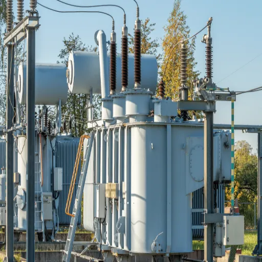
Understanding Vector Group Designation
A vector group of transformer tells the way by which the -coils of a transformer is connected and the phase difference extent of the winding and winding of its primary and secondary windings. Consequently, a vector group is essential for the installation of a transformer and ensures that capacity is shared properly and that fault management is carried out in complex electrical networks.
Vectors and groups of phase symbols are made up of Y for wye or star, D for delta, and Z for zigzag, just followed by numbers indicating how far apart the phase is at 30-degree intervals after each of the symbols. For example, Yyn0, as the abbreviation implies, represents a star-star, with both windings separated by 0° phase displacement. On the other side, Dyn11 is delta on primary winding with -star on secondary winding at 330° with respect to -30° phase shift.
Key Components of Vector Group Designation:
- Connection Type:
- Star Connection (Y): In a star connection, which is well-suited for unbalanced loading, one can achieve neutral grounding.
- Delta Connection (D): Suitable for high-power transmission, and the closed loop provides a path for harmonic currents.
- Zigzag Connection (Z): It serves excellent grounding, which is used for compensation of harmonics and fault current management.
- Phase Displacement:
- Such a note is shown in a clock-hour figure in which the primary windings are indicated by the hour hand and the secondary by the minute hand. For example, Dyn11 is known because it shifts the phase by -30 degrees (Primary at 12 and Secondary at 11).
- Application Specific Application:
- In practice, Yyn0 frequently finds application in renewable energy sources such as wind farms and solar power plants due to the neutral effective grounding.
- Dyn11 transformers with, for example, displaced phases are usually applied in industry to reduce the impact of harmonics.
Understanding the correct vector group ensures that transformers function seamlessly in their intended networks, avoiding issues like circulating currents or improper fault response. Detailed analysis of these designations helps optimize energy transmission, contributing to the reliable performance of modern energy systems.
Notation Explained: Phase Shift and Connections
A transformer-vector group is actually an expression of the relative amounts of phase shifts that occur within the primary and secondary windings, as well as the way in which these windings are constructed. In this manner, accuracy is achieved, and the systems guarantee that a power supply will be in a rest condition and peaceful. The most common is that of the Delta(Δ)winding and the Y or Star windings. Typical classifications such as “Dyn11” or “Yd5” refer to the features in addition to a variety of specifications.
For instance, in the particular case of “Dyn11”, “D” corresponds to a delta-connected primary, while “Y” to a wye-connected secondary. The numbers-“11”-usually only indicate a logically expected 30-degree lead difference between the windings (calculated based on a clock representation wherein 12 is zero degrees). Depending on the requirements, a particular choice for such an arrangement might be made – that is, whether to balance the load, reduce harmonics, or eliminate circulating currents in the circuit.
The data discloses that the reliability of a transformer depends a lot on the selection of accurate configurations used in industry and grid world applications. For instance, from studies held by IEEE, it was found that connecting the transformers in parallel with a mismatched vector group caused circulating current that increased the losses up to 20%, which further reduced the efficiency of the system. There has also been the entry of nonlinear loads that have produced more harmonics in these systems. Because of this, new shapes of “Zig-Zag” will turn out to filter distortions better, while some designs are capable of filtering about sixty percent of THD.
It demonstrates how important vector linkage and reasoning is in the power systems context of recent years. Especially in the modern-day system, it uses many different software tools and simulators to model and predict the behavior of the system under a certain configuration of the vector group to create an efficient and reliable system.
Interpreting Vector Group Designations from Nameplates
The nameplate of the transformer is the most important thing that can help understand many of these descriptions about vector groupings. The phase and winding will be mentioned, and then this can be read from the same plate, the reading of which could help in understanding transformer behavior in a power system. This list needs you to get used to some letters and figures, such as Dyn11 or YNd1. Though the capital letter signifies the primary winding connection (Delta times or Star), the lowercase letter indicates the secondary connection of the winding (delta or Star), while the number gives the phase displacement in clock-hour notation.
As per industry reports and data available nowadays, Dyn11 is seen globally used in about 40% of transformers, and this might be due to its effectiveness in reducing zero-sequence currents and minimizing harmonic distortions. Simulations further indicate that some specific sets of vector groups, such as Yd1, have been making more effective networking due to companies currently following an increased demand for networked supplies and hence better stability in voltage compared to other vector sets.
From having become possible recently, with the analysis of large volumes of operational data, mostly with diagnostic software to a profound intelligent control system, it is also found that the transformers are becoming more easily examined at the site. Infrared thermography and load profile data may identify all possible misalignments or inefficiencies in terms of group arrangements with such kinds of diagnostics. So to focus on every operational data, this means having the most intense work ethic and would definitely mean much more effective deployment of the transformers and a very big part of the equipment, which is performance as well for the service area, such as industrial grids or any energy renewals.
Verification Tests for Transformer Vector Groups
Standard Testing Methods
There are normal procedures for testing that substantiate the value of the vector group, starting with it. This series of TCR tests keeps the transformers configured and optimally functional. A comparison can be made between the primary and secondary voltage lines in terms of alignment with the specification of the vector group through phasor diagram measurements. Polarity test reveals how accurately the windings have been arranged because of the positive and negative windings they have.
Thus, it is a secure and dependable way, with other methods, the three-phase voltage test or better known as the short-circuit test goes considerable support too. This three-phase voltage is applied to specific windings for measuring phase differences, while the observed differences are taken to the calibrated instruments during vector grouping validation. By what has been seen, this has come to have been advanced in the traditional method due to cutting-edge advancements and comprises a tool or software solution that can make the entire phase relationship verification really easy and automate it with the Digital Signal Processing (DSP).
Said source can tell that infrared thermography measurements can diagnose the spaces “online” as soon as they start coming out of alignment in a machine, even a simple hot spot might mean that the vector-group connection is wrongly configured. Presently, the testing now shifts online with SCADA (Supervisory control and data acquisition) systems to show real-time monitoring of angle, the essential event to monitor proper functioning of the transformer.
According to statistics, inconsistent locations account for as much as 85% of transformer failure experience. This spells one word, and that is the true necessity of very reliable testing. In addition, these advanced test measures incorporate further automatic monitoring aids and ways for maintaining risk management and enhancing reliability, specifically in complex power systems, such as smart grids and renewable energy systems, for proper energy input.
How to Conduct Verification Tests
Transformer vector group configurations are checked in an organized manner for compliance with principles. The latest research information about industry trends currently suggests that most of these frailties are starting to be taken care of by most of the major players in the marketplace. This can be achieved with the application of more sophisticated digital relay test sets to assure a greater amount of precision and a minimal degree of human contact. An ordinary test process is a three-phase, voltage-known-tested process where the phase shift and the connection type are found correct if the voltage is applied to one side of the transformer and the output is taken from the other side after measuring.
Most literature and research conclude further that the time taken in testing could be reduced by 40%, but results get improved by up to 25% using such automated testing tools. The algorithms used are very sophisticated in detecting even the slightest fault in the configuration, and this makes the process even more worthwhile within the grid.
Those tests need to pass the whole guarantee of the standards of IEC 60076-1 and IEEE C57.12. In their own way, these tests are meant to check facets such as polarity checks, ratio tests, and verification of vectors of the transformer that ensure adequate rather than coercive long operation for the transformers. Again, when an automatic monitoring system is installed, data analytics helps the operators to keep historical performance data and plan for recovery when they see that the system is going to hit soon, so as to avoid it.
Interpreting Test Results
Analysis of test results should not be carried out without inspecting the data and verifying the correct functioning at the time, ensuring no fault is noticed afterwards. Few examples could be provided by the testing approach, but the ratio test appeared to be among the most essential tests that connect the primary and secondary voltages and give a possible public talk about the short circuits or the windings’ problems if there was any deviation from the nominal ratio, in whichever direction that may be. To put this in an absolute context with respect to power transformer over-testing, the tolerance on the ratio test is normally ±0.5%. Meanwhile, polarity checks will close in on their connection with the designed expectations, which is important in knowing whether the generated faults are phase-related faults in systems with more than one transformer.
Moreover, Vector Group confirmation could be counted as an implication, as the signaling of coherent phase structure for a transformer. Deviation under the Vector Group of the transformer, as per the standard of IEC 60076-1, can potentially lead to operational malfunctions or total failure situations. Improvement brings data in the domain where historical working norms are not prior as it is supported by an extended monitoring; there is also the development of recycling, regeneration, and repair processes in them. Industry’s most recent reports point out a 30% reduction in transformer failure events in any proactive program applying predictive analytics on a larger scale, hence ensuring a safer means through which to discern the issue before it is escalated.
Among these diagnostic tests are analyses for dissolved gas, which mirrors what is happening inside the transformer by identifying those critical gases that would be created in the event of thermal overloading or electrical fault. Detection is possible through measuring hydrogen (H2) and acetylene (C2H2) concentration in standard testing samples, as an increase of their levels should point to the presence of partial discharge or arcing. Correct comprehension of the testing results is a necessary part, not only in terms of technical know-how, but also because of what the industries have brought into standards, such as the IEEE C57.12 guidelines, in order to give proper evaluations and assessments.
Reference Sources
- 1 X 1000 Kva Transformer Measurement Analysis Using Vector Group Dyn-11 and Off-Load Tap Changer
This study analyzes the performance of a 1 x 1000 KVA transformer using the Dyn11 vector group, offering practical insights into its application.
Read more here - Distribution Transformer Synchronization Simulation with Two Different Vector Groups using Matlab Simulink
This research focuses on synchronizing Dyn5 and Dyn11 distribution transformers and provides insights into their vector group characteristics.
Read more here
Frequently Asked Questions (FAQs)
What is the importance of a transformer vector group?
The winding arrangements and the relative phase angle differences on the primary side and the secondary side bring reference quantities, making the life of the electrical engineer easy in knowing how the poles should be connected, along with several other activities. With respect to the types of the above, the vector group of each of the apparently other actually dissimilar transformers will lead to judging the quantum of the respective quantities of impedance connected in it. Such data helps in choosing the appropriate one that assumes the transitional assignment mode into the system requirements and promises the correct operation in parallel.
How is Dyn-11 explained in transformer vector groups?
It’s a mathematical identity for vector group provision in a transformer. Dyn11 means that the primary winding is delta-connected and the secondary winding is primarily connected in star (Y) connection, and there is a midpoint. In dyn11, “11” refers to the degree of phase shift between primary and secondary winding. This means that the windings are out of phase at 30 degrees.
What are the main characteristics of the transformer called Yyn0?
In this transformer, the primary and secondary coils are star-connected, and access is provided to the neutral point of the two coils. The name ends with 0, meaning that it has primary and secondary coils without any phase difference. These are extensively used in systems like balanced neutral currents and zero-phase shifts.
How is the vector group of the transformer related to parallel operation?
For paralleling two transformers, both vector groups should either be the same or follow each other, because for proper working and in respect of circulating currents, it is not permissible to combine transformers from different vector groups. Double or major parts of the load on one transformer may cause a malfunction. Transformers or equipment within systems are damaged because of a failure to have parallel phase shifts due to multiplier errors of vector groups, which bring imbalance and potentially harm transformers and even system equipment.
What is IEEE C57.12 in relevance to the vector groups of Transformers?
IEEE C57.12 norms provide stipulated general standards about architecture, examination, and performance requirements for transformers. Construction specifics, like winding arrangements, phase shift, and other critical features, are identified to ensure that transformers work within the required functions well and consistently.
Where are Dyn11 and Yyn0 transformers typically used for?
For distribution grids, Dyn11 transformers are commonly deployed and are designed to keep the harmonics under control and shift the imbalance at the bottom by 30 degrees. On the flip side of the coin, Yyn0 transformers are intended for the cool distribution load that requires no phase shift and instead only gets a balanced distribution; heavy supply for industrial and generator applications.