
Underground Pad Mount Transformer: Complete URD System Guide
What nobody realized was how essential the electricity supply was until the largest blackout in the history of the United States occurred due to the storm Sandy in October 2012. Along the Sandy coast, devastated neighborhoods with traditional overhead power lines had to live in darkness without electricity for weeks or sometimes more, given the number of poles toppled by trees and wires dangling across streets. However, in affected newer developments with underground residential distribution systems, families had their service restored within days, if not hours. It was really buried beneath their feet, their very difference.
Underground distribution systems represent a fundamental alteration in how people think about power, reliability, safety, and community resilience. Engineers, developers, and utility planners now specify underground pad-mount transformers because they serve as the backbone of the modern distribution network. The real challenge is how to design such systems correctly from the start.
Understanding what underground pad mount transformers are – The guide gives basic information about these devices. Among the topics to be discussed are the URD system structure, conformity to IEEE standards, as well as NEC installation requirements and cable integration. This information is intended to be of great help: You can design a new residential sector, update the industrial swath you have on hold, and provision in export markets.
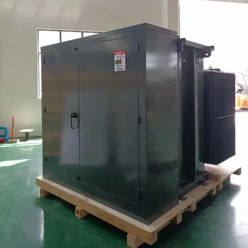
What Is an Underground Pad Mount Transformer?
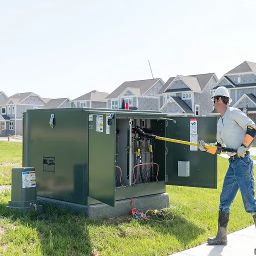
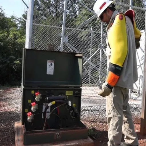
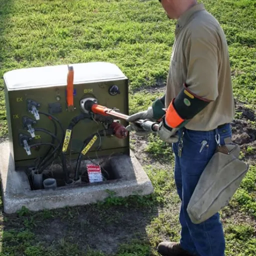
A pad-mounted transformer is an electric transformer previously somewhat stored at ground levels but later in a locked steel enclosure discouraging acts from the outside. This type transfers buried primary cables under the ground to obtain the power, opposite to power poles connecting to overhead lines. These transformers lower high-voltage current to suitable home or business levels.
The ‘pad mount’ of the term stems from a concrete foundation that supports the transformer under these categories. These transformers are at grade level so that maintenance can be performed without excessive visual clutter brought about by overhead power lines. They then come in a green-colored cabinet, indicative of the presence of high voltage inside the unit.
Underground Pad Mount Transformers act as distribution nodes in URD (Underground Residential Distribution) systems with primary cables running underground from substations to these transformers. From the transformers, secondary service lines are used to supply power to individual buildings, clearing almost all overhead wiring within the service area.
Want to explore how pad mount transformers compare to other distribution methods? Read our complete pad mount transformer guide for detailed specifications and selection criteria.
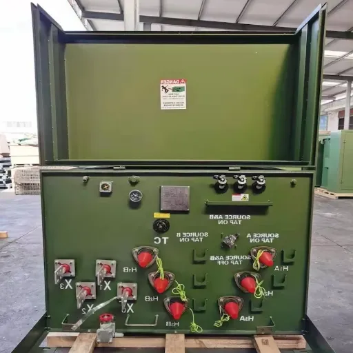
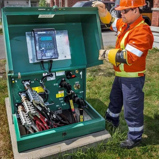
Key Components of Underground Pad Mount Transformers
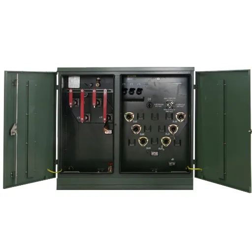
Steel Enclosure: It addresses cover lockout provisions and intentional bypassing control. It has to comply with IEEE C57.12. 28 field conditions in air-to-ground and environmental ratings.
Transformer Tank: Whether oil-filled or windings composed of dry construction, the standard is never any tank sealing, and yet magnetic flux paths are trapped within the core-shell of the iron core connected with a concentration of outer layers.
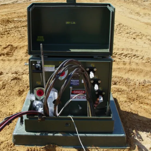
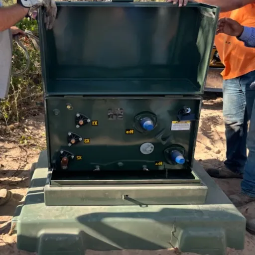
High-Voltage Terminations: Interruptible load Bushing and separable insulated connectors function as the connectors for primary cables to tap the load. In normal operation, the parts of the energized front systems are kept dead.
Low-Voltage Bushings: Offering a secondary terminal connection with feeds from sidewall cables, which feed the building size, including 120/240V single phases or 208Y/120V three phases and 480Y/277V three phases.
Protection Equipment: Current-limiting fuses, bayonet fuses, and surge arresters protect the transformer side of the system and all succeeding components from system issues and lightning disturbances.
Underground Distribution: Why Utilities Are Going Underground
The shift toward underground distribution accelerates each year. According to industry surveys, approximately 65% of new residential developments in North America now use URD systems. The reasons extend far beyond cosmetic improvements.
Reliability Improvements
Climate conditions cause about seventy percent of power supply discontinuities, as in the case of overhead layers. Ice storms and high wind throws, falling trees – the power disturbance caused by such reasons is a familiar routine occurrence. Such vulnerabilities were eliminated by the underground distribution system. Utilities have noted appreciably lower numbers of weather-related outages-50% to 70% less.
The most significant effect that can be seen for reliability during severe weather is prominently shown after the hurricane, Hurricane Ian, which decimated Florida in 2022. This was when neighborhoods with an underground distribution network could still have power as opposed to those other neighborhoods with overhead lines, and had to only wait for repairs to last weeks. This is why the higher initial investment will be recouped by many utilities.
Safety and Aesthetics
Eliminating overhead lines removes safety hazards from public spaces. No poles for vehicles to strike. No downed wires after storms. No access issues for aerial lifts and bucket trucks near power lines.
Aesthetic improvements increase property values. Studies consistently show that homebuyers prefer underground utilities and will pay premiums for neighborhoods without overhead lines. Developers use underground distribution as a selling point for premium residential communities.
Urban Planning Benefits
Underground distribution frees streetscapes for other uses. Sidewalks need not navigate around utility poles. Landscaping and tree planting face fewer restrictions. Street lighting and traffic signals integrate more cleanly without overhead wire conflicts.
URD System Architecture: How Underground Distribution Works
Underground Residential Distribution systems follow a hierarchical design. Understanding this architecture helps engineers specify appropriate equipment and plan effective layouts.
Primary Distribution Network
High-voltage primary cables (typically 12.47 kV, 13.2 kV, 24.94 kV, or 34.5 kV) carry power from substations throughout the service area. These cables use cross-linked polyethylene (XLPE) insulation rated for 90°C operation. Concentric neutral wires provide return paths and fault current-carrying capacity.
Primary cable sizing depends on load density and voltage drop calculations. Common conductor sizes range from #2 AWG for lighter loads to 1000+ kcmil for heavy commercial applications. Utilities typically size primary cables for 20-30 years of load growth.
Transformer Placement and Sizing
Pad mount transformers sit at strategic locations based on load centers. Residential transformers typically serve 4-8 homes per unit. Commercial applications may require dedicated transformers for individual facilities.
Transformer sizing follows load calculations with diversity factors. A group of homes rarely draws a full-rated load simultaneously. Engineers apply diversity factors (typically 0.6-0.8 for residential) to avoid oversizing equipment while maintaining voltage quality.
Single-phase residential transformers range from 25 kVA to 167 kVA. Three-phase commercial units span 150 kVA to 3000+ kVA. Standard secondary voltages include 120/240V single-phase and 208Y/120V or 480Y/277V three-phase.
Secondary Service Laterals
From each transformer, secondary service cables run to individual buildings. These 600V-class cables use aluminum or copper conductors with XLPE insulation. Common configurations include:
- Duplex: Two conductors for 120/240V single-phase service
- Triplex: Three conductors for single-phase with neutral
- Quadruplex: Four conductors for three-phase service
Service lateral sizing depends on load requirements and distance. Voltage drop limitations (typically 3-5% maximum) often govern conductor selection more than ampacity.
Loop Feed vs Radial Feed Configurations
URD systems use two primary configurations for primary cable routing. Each offers distinct advantages for reliability and cost.
Radial Feed Systems
In radial configurations, a single primary cable runs from the substation to the transformer. The cable terminates at the transformer without continuation. This is the simplest and least expensive configuration.
Advantages:
- Lower cable costs
- Simpler protection coordination
- Straightforward fault location
Disadvantages:
- No backup path if the cable fails
- Outages affect all downstream customers
- Less suitable for critical loads
Radial feeds work well for low-density residential areas where reliability requirements are moderate and cost sensitivity is high. They represent the majority of residential URD installations.
Loop Feed Systems
Loop configurations use primary cables that go past the transformer, forming a complete circuit back to the substation or another feed point. They have switches at each transformer that probably stop the isolation of faulted sections but maintain service to the remaining customers.
Advantages:
- Automatic switching restores service during cable faults
- Minimal customer outages for primary cable failures
- Higher reliability for commercial and critical loads
Disadvantages:
- Higher cable costs (roughly double radial systems)
- More complex protection and switching equipment
- Higher maintenance requirements
Loop feeds dominate commercial installations, critical facilities, and premium residential developments. The additional cost typically pays for itself through reduced outage costs over the system’s lifetime.
Need help selecting between transformer configurations? Our distribution transformer guide provides detailed selection criteria for various applications.
Technical Specifications and IEEE Standards
Underground pad-mounted transformers must be the best in terms of safety, reliability, and interoperability requirements. For design, testing, and installation, IEEE standards define very clear guidelines.
IEEE C57.12.34: Three-Phase Compartmental Type
IEEE C57.12. 34-2022 specifies requirements for three-phase, 60 Hz, liquid-immersed, self-cooled, pad-mounted, compartmental distribution transformers. It covers distribution transformers rated 10 MVA and less with a high voltage rating to 34.5 kV and a low voltage rating to 15 kV.
Key requirements include:
- Electrical Characteristics: Standardized impedance and BILs can be used according to the voltage of the transformer.
- Enclosure Design: High-voltage and low-voltage compartments are separated. Doors are lockable, limiting entry to only a few authorized personnel. The tamper-resistant feature will avoid unwanted entry.
- Safety Features: Dead-front primary connections have separable insulated connectors (within IEEE 386) so that energized parts are not reachable. There are also relief devices for preventing the tank rupture within.
IEEE C57.12.38: Single-Phase Standards
As far as single-phase pad-mounted transformers for underground distribution are concerned, this is defined by the IEEE C57.12. 38 standard. These transformers, averaging from 15 to 167 kVA residential loads, go to single-phase underground distribution. The standard includes ratings up to the extensive transformers; as there are many such transformers, they begin with a rating of 500 kVA and primary voltages extending to 34.5 kV.
Single-phase transformers will also be rated just as they are constructed to withstand major overloads as three-phase system units. Among the other features, the dead-front devices also account for a relatively small part of the market growth, while the application of live-front devices is limited to certain installations.
IEEE 386: Separable Insulated Connectors
Equipment included in that standard includes load-break elbows, bushings, and accessories, all of which are on underground distribution systems. These allow you to:
- Energized cable connection and removal: The Cable can be made or interrupted without disconnecting the primary power pole by trained workers.
- Visible break point: An elbow termination that exhibits an isolated state
- Current interruption: 200A or 600A load break ratings allow efficiencies for switching against mag current from the transformer.
Connector systems should match between the transformers and the cables. With this load, the standard 200A as well as the 600A rating is accommodated with different stages of load service. Understanding of fault-current ratings and load-break capabilities is also necessary for its correct use.
Other Applicable Standards
IEEE C57.12.28: Requirements for Aggregation Integrity of Pad-mounted Equipment, incl. Resistant to Violation and Environmental Protection
IEEE C57.12.00: General Aspects of Liquid-immersed Distribution Transformers, Including Loss Evaluation and Limitation of Bounds for Suspension
IEEE C57.12.90: Test Code for Liquid-Immersed Transformers on Standard or Routine, kind, and design tests.
NEMA TR1: Transformer voltage ratings and basic insulation levels for specific voltage classes.
NEC Installation Requirements and Clearances
The National Electrical Code (NEC) establishes minimum safety requirements for transformer installations. Article 450 covers transformers and transformer vaults, while Article 110 addresses general installation requirements.
Working Space Requirements
As per NEC 110.34, 600 volts of electrical equipment should have a clear work area as follows:
- Front (access side): Minimum 3 feet (0.91 m) clear working space
- Sides and rear: Minimum 3 feet for ventilation and maintenance access
- Headroom: Minimum 6.5 feet (2 m) vertical clearance
- Grade: Working space must extend to the Grade or working platform level
Many utilities exceed these minimums. Hot stick operations, boom truck access, and safety considerations often raise the requirement to 8-10 feet before any space in front. Do not finalize designs unless and until the specific utility requirements have been verified.
Building Separation Distances
NEC 450.21 addresses transformer clearances from buildings:
- Combustible construction: A minimum of 12 feet from combustible walls or materials
- Non-combustible construction: A minimum of 6 feet from building walls
- Openings: A minimum of 10 feet from doors, windows, or other openings
- Fire escapes: A minimum of 20 feet from fire escapes, stairways, or exits
These rules apply to oil-filled distribution transformers that have a content of flammable liquid exceeding 35 gallons. Such clearances can be decreased for less-flammable liquids (such as natural ester or silicone, or high-flash-point hydrocarbons) if approved by the authority.
Site Preparation and Pad Construction
Transformers require properly constructed concrete pads that provide:
- Level surface: Pad must be flat within 1/4 inch per foot to ensure proper oil level and bushing alignment
- Load capacity: Must support transformer weight plus maintenance personnel and equipment
- Dimensions: Typically 6-12 inches larger than the transformer base on all sides
- Height: Pad should extend 4-6 inches above finished grade to prevent water pooling
- Grounding: Grounding electrode conductor connections must be accessible
Pad construction details vary by transformer size and local soil conditions. Engineers should provide stamped drawings showing dimensions, reinforcement, and anchorage requirements.
Grounding Requirements
NEC Article 250 also states that all transformer installations must be effectively grounded:
- Equipment grounding conductor: Bonded to the transformer itself or its enclosure
- Grounding electrode: Attached to the ground rods, ground rings, or other approved electrodes mentioned.
- Neutral grounding: The grounding of the secondary neutral at the transformer site.
- Conductor sizing: Scalability of earthing conductors in line with NEC table 250.66 and 250.122
A good grounding is necessary to protect people who come into contact with electrical components from shock hazards in operations, as well as to pass fault currents between any protective devices. The ground resistance should not be more than 25 Ohms; the lower the better.
Underground Cable Systems Integration
Underground pad mount transformers connect to cable systems that differ significantly from overhead wiring. Proper cable selection and termination ensure reliable operation.
Primary Underground Cables (5-35 kV)
Shielded constructions use primary distribution cables and have the following general features:
Conductor: Aluminum or copper, densely stranded and compressed. Aluminum is common because it is cheaper and lighter; typical sizes run from #2 AWG to 1000 kcmil.
Conductor Shield: Extruded semiconducting layer for conductors and interface insulation, smooth.
Insulation: Croes-linked polyethylene (XLPE) or tree-retardant XL-AR-xLPE rated at 90°C continuous, varies in thickness with voltage class (90 mils for 15 kv, 175 mil for 35 kv typically).
Insulation Shield: Extruded semiconducting layer bonded to insulation, covered with a metallic shield.
Metallic Shield: A concentric arrangement of copper wires at typically 1/3rd the ampacity of the phase conductor is a low-resistive path and a carrier of capacitive current.
Jacket: Linear low-density polyethylene (LLDPE) with extruded identification stripes, which prevents any physical or atmospheric damage from squeezing the twist and creates a moisture path towards the cable’s exterior if such damage should occur.
Cable Termination Methods
Primary cables terminate at pad mount transformers using load-break elbows and bushings:
200A Load-Break Elbows: The standard for most distribution transformers. These separable connectors install on dead-front bushings and allow energized connection and disconnection. The elbow assembly includes:
- Probe contact for electrical connection
- Insulated elbow body with test point
- Cap or parking stand for isolation
600A Load-Break Elbows: Used for larger transformers and higher current applications. Similar construction to 200A but with heavier current-carrying components.
Installation Requirements: Proper cable preparation is critical. Semiconducting layers must be cleanly stripped with precise dimensions. Stress control materials manage the electric field distribution at terminations. All work must follow manufacturer instructions and IEEE 404 standards.
Secondary Distribution Cables
Simple construction is used by secondary service cables with (600V class).
Single-Conductor URD Cable: Aluminium conductor with XLPE insulation. For individual phase and neutral conductors in open trench installations.
Duplex Cable: Two conductors comprising phase and neutral conductors twisted together. This is meant for single-phase 120/240V service.
Triplex Cable: Three twisted single-phase service conductors having a full capacity neutral or three-phase delta service.
Quadruplex Cable: Four conductors twisted together, otherwise three-phase wye services.
Conductor sizing purely depends on load amperage capacity and voltage drop limits. This can be seen from the NEC Chapter 9 tables that provide amperage ratings. For voltage drop calculations, the total drop should not exceed 3% for power, heating, and lighting loads, or 5% from mixed loads.
Sizing Transformers for URD Applications
Proper transformer sizing ensures adequate capacity for current loads while providing margin for future growth. Undersizing leads to overload conditions and shortened equipment life. Oversizing wastes capital and may result in poor voltage regulation at light loads.
Residential Load Calculations
Single-family homes typically use 25-75 kVA transformers, though larger homes with electric heating or EV charging may require 100 kVA units. Load calculations consider:
Connected Load: Sum of all electrical equipment ratings in the home. This includes HVAC, water heaters, appliances, lighting, and general receptacles.
Demand Factors: Not all equipment operates simultaneously. NEC Article 220 provides demand factors that reduce the calculated load based on the probability of simultaneous use.
Diversity: A transformer serving multiple homes benefits from diversity among loads. While one home may peak during morning hours, another peaks in the evening. Diversity factors of 0.6-0.8 typically apply.
Example calculation for a 167 kVA transformer serving 8 homes:
- Average home connected load: 25 kW
- Total connected load: 200 kW
- Demand factor (per NEC): 0.35 = 70 kW
- Diversity factor: 0.7 = 49 kW estimated peak
- 167 kVA transformer provides 3.4x margin over estimated peak
Commercial and Industrial Sizing
Commercial loads lack the diversity benefits of residential applications. Each facility must be evaluated individually:
Load Inventory: Catalog all electrical equipment with operating characteristics. Include motors, HVAC, lighting, data equipment, and process loads.
Load Factor: Consider diversity within the facility. Motor load factors, duty cycles, and simultaneous operation affect peak demand.
Future Growth: Size transformers for 20-30% growth beyond current requirements. This avoids premature replacement as loads increase.
Power Factor: A low power factor increases reactive power requirements. Consider power factor correction capacitors to reduce transformer sizing needs.
Voltage Drop Considerations
Transformer sizing affects voltage drop throughout the distribution system. Higher transformer capacity provides better voltage regulation but requires larger primary cables and protection equipment.
Standard practice designs for a 2-3% voltage drop from the transformer secondary to the furthest service point. This ensures adequate voltage at all customer locations under peak load conditions.
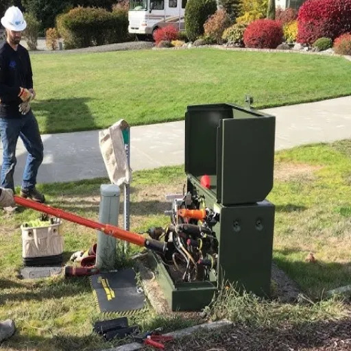
Installation Best Practices
Successful URD installations require attention to detail throughout the construction process. Following industry best practices prevents costly rework and ensures long-term reliability.
Site Selection and Preparation
Location Criteria: Select sites that meet clearance requirements, provide maintenance access, and minimize environmental impacts. Consider:
- Proximity to load centers
- Proximity to existing primary cables
- Vehicle access for installation and maintenance
- Drainage and flood potential
- Future expansion needs
Trenching and Cable Routes: Plan cable routes that minimize crossings and follow established utility corridors. Maintain minimum separation from other utilities:
- 12 inches from gas lines
- 12 inches from water lines
- 18 inches from sewer lines
- 24 inches from communication cables
Soil Conditions: Assess soil corrosivity, thermal resistivity, and mechanical stability. Aggressive soils may require special cable jackets or cathodic protection. High thermal resistivity soils may require cable derating or thermal backfill.
Transformer Placement
Receiving and Unloading: Transformers are filled with the insulating liquid upon arrival. Take the necessary care to avoid collision damage. Use proper lifting equipment rated for the transformer’s weight plus rigging.
Pad Installation: Ensure that the pad is levelled and ready to be used for transformer placement. Drop the transformer down on the pad without any backlash or impact. Enable the transformation of the primary and secondary points of codification with the transformer.
Anchorage: Anchor the transformer on the pad using the specified anchor bolts provided by the manufacturer. Tighten per the defined torque. The proper anchorage would hold the transformer stationary when pulling the cable, either from a seismic displacement or from a vehicle impact.
Cable Installation
Pulling Tension: The other thing also important to heed is not to exceed the maximum pulling tension during the cable installation. The running limit must be followed by referring to the datasheet specifications of a conductor size and material. Apply using a proper pulling lubricant to reduce pulling friction.
Bending Radius: Ensure that the minimum bending radius (usually 12x cable diameter for shielded power cable) is not below safe limits, damaging the insulation. Sheaves and rollers should be sized accordingly.
Splicing: Make sure there are fewer primary cable splices. Use prefabricated or heat-shrink splicing kits suitable for system voltage where required. Follow instructions from the manufacturer.
Termination: Cable ends need to be cleaned and prepared per the manufacturer’s elbow specifications. Control of the removal of the semi-conducting layer is critical for long-term requirements. Take all terminations to the specified torque values.
Testing and Commissioning
Before energizing new URD installations, perform these tests:
Cable Testing:
- Insulation resistance testing (megger) phase-to-phase and phase-to-ground
- High-potential (hipot) testing to verify insulation integrity
- Partial discharge testing for critical installations
Transformer Testing:
- Turns ratio testing to verify proper winding ratios
- Winding resistance measurements
- Insulation power factor or dissipation factor testing
- Excitation current testing
System Testing:
- Phasing verification to ensure proper rotation
- Load flow testing under actual load conditions
- Protection device coordination verification
Document all test results for warranty and maintenance records.
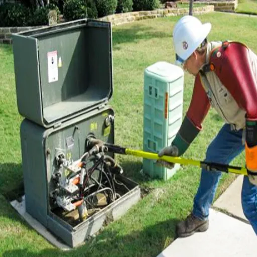
Maintenance of Underground Transformers
Underground pad mount transformers require less maintenance than overhead units, but regular inspection prevents minor issues from becoming major failures.
Visual Inspections
Conduct visual inspections quarterly or biannually, elucidated as follows:
Enclosure Condition: Check for physical changes to the enclosure, such as rust, corrosion, physical damage, or breaking in. Verify all doors and locks function properly.
Oil Level: Check the sight glass if it is liquid-filled. For the oil level, when the level is low, it will only mean leaks or internal problems, and therefore, one needs to examine what these could be.
Surrounding Area: Clear away vegetation and debris from the pad area, maintaining at least 12 inches of clearance around the enclosure. Ensure grade drains away from the pad.
Warning Labels: Ensure the legibility and original presence of all safety signs or labels. Replace faded/damaged labels.
Electrical Testing
This is how, once or twice a year, testing is done on the electrical side to monitor the condition of the transformer:
Infrared Scanning: Hot spots are identified by thermal images, which will show where current is leaking, causing circuits to overload or grounds to go awry. A full scan of all terminations, bushings, and accessible conductors.
Oil Analysis: Once taken for liquid-filled transformers, it detects internal faults using dissolved gas analysis (DGA). Based on the oil sample revelation:
- Combustible gas levels indicating overheating or arcing
- Moisture content affecting dielectric strength
- Acid levels indicating insulation degradation
Insulation Resistance: An insulation-megger test is performed periodically, and it charts the insulation’s nature gradually as time evolves. A clear indication that resistance declines may be the encumbrances of aging or pollution in the bearing of an individual’s attention.
Vegetation Management
Plants and trees threaten underground cable systems. Root damage to cables causes difficult-to-locate faults and expensive repairs.
Maintain clear zones around transformers and along cable routes. Use barriers or root guards where trees must remain near underground facilities. Document tree locations for future reference.
Cost Analysis: Underground vs Overhead Distribution
The economics of underground distribution differ significantly from overhead systems. Understanding these differences helps justify investments and set appropriate customer contribution policies.
Installation Cost Comparison
Putting cables underground typically costs 2-5 times more compared to the overhead counterparts’ prices. Main expenditures include the following:
Cable and Accessories: The meter cost of underground primary cable is usually about three times greater than that of overhead wire per foot, plus costs for elbows and terminations, and accessories.
Excavation and Restoration: Trenching, backfilling, and surface restoration add significant labor and material costs. Rock excavation or directional boring further increases costs.
Transformers: Pad-mounted transformers are typically more expensive than pole-mounted transformers; they are housed in a concrete enclosure with safety features. Concrete slab placement adds material and labor.
Switching Equipment: Loop-feed systems add additional sectionalizing switches and automation equipment.
Underground distribution can vary between $15,000-25,000 per lot and $4,000-6,000 for overhead. Such numbers depend on local conditions, types of soil, and density across subdivisions.
Lifecycle Cost Considerations
While initial costs favor overhead systems, lifecycle costs tell a different story:
Maintenance Savings: Underground systems require less ongoing maintenance. No tree trimming along rights-of-way. Fewer storm damage repairs. Reduced vegetation management.
Outage Cost Reduction: Improved reliability translates to fewer customer outage minutes. For commercial and industrial customers, avoided outage costs often exceed the installation premium within 10-15 years.
Infrastructure Longevity: Underground cables and transformers typically last 40+ years with proper maintenance. Overhead systems face faster degradation from weather exposure.
Property Value Impact: Studies show 5-10% property value premiums in neighborhoods with underground utilities. This increased tax base benefits municipalities.
Developer Contribution Policies
Most utilities require developers to pay the differential cost between overhead and underground service. Common approaches include:
Full Differential: Developer pays the entire cost difference between overhead and underground installation.
Standard Allowance: Utility provides credit for standard overhead installation cost. The developer pays any amount above this allowance.
Underground Mandate: Some jurisdictions require underground utilities in new developments. Costs are built into lot prices.
Amortization Programs: Large developments may amortize underground costs over multiple phases or years.
Conclusion
The Underground Pad Mount Transformer is the foundation on which the URD systems of the present generations sustain, so as to provide electricity and for a long time, while taking the visual beauty of the people to clean and clear air. Deciding on going underground as opposed to an aerial network would at all times mean accepting the relatively higher up-front costs in exchange for many years of improved security, security maintenance, and increasing prime cost of the properties.
One must understand that policies, systems, and standards are very important for every successful implementation. The IEEE handles the scientific aspect in detail. NEC declarations cater to safeguards. Utility requirements aim at particular surrounding situations.
For those like engineer merchants, engineers, and utilities design consultants should sort out those types of systems and pick up at which point in time, and/or in which section of the structure/area having an underground solution is rational. There is a potential advancement in the national grid system with the introduction of the smart grid, monitoring systems, and better cables.
Ready to specify underground pad mount transformers for your next project? Contact our engineering team for custom solutions tailored to your specific voltage, capacity, and configuration requirements.
Frequently Asked Questions
How deep are underground power cables buried?
Primary distribution cables usually require 30 to 36 inches of cover in residential areas and up to 42 inches in commercial or vehicular traffic areas. Secondary service cables usually need 18 to 24 inches of cover, but up to 3 feet might be required if provided by a local amendment.
What is the life expectancy of an underground pad mount transformer?
Pad-mount transformers with proper maintenance can last 25 to 40 years. Appliances located in mild-temperature regions and with low loads could extend for more than 40 years. Severe climate conditions, as well as overloading and poor conservation, will cut down the overall number of years.
Can underground transformers be flooded?
Pad-mounted transformers are outdoor installations. They can endure temporary immersion, but long exposure to submerged conditions could harm the equipment. After flooding, they need to be closely inspected and tested before they can be energized. If possible, plan to elevate transformers located in flood-prone areas above the base flood elevation.
How do you locate a fault in underground cables?
Cable fault location is done with the use of TDR, HV impulse, and, in some cases, acoustic fault location. It sends pulses down the cable and then analyzes the reflections to determine the position of faults. It requires digging at the point where the fault takes place in most cases.
What is the minimum distance from a building for a pad mount transformer?
The NEC states that a 12-foot clearance from combustibles and a 6-foot clearance from non-combustibles was tricky to explain, yet most utilities regulate their distances to 10 feet for everything. Always check with your utility’s rules, which usually are stricter than those proposed in the NEC.
Are underground transformers more reliable than overhead?
Underground systems encounter about 50-70% fewer shutdowns than overhead counterparts, mostly owing to eliminating conditions that are weather-dependent. Underground outages are found and rectified over a longer period of time when they do occur.
How much more does underground distribution cost?
A well-managed urban underground system is normally around three to five times higher in the beginning, though, in the long run, the upfront overhead is usually balanced by the lower maintenance and higher reliability.