

Pad Mount Transformer: Complete Buyer’s Guide & Specifications

Considering proposed residential development requirements, a utilities engineer in Phoenix was ruling on a high-stakes infrastructural decision. Overhead power lines would detract from the beauty of the community and violate zoning laws in the locality. However, under circumstances that allow only eight weeks for transformer procurement and installation, underground distribution was the only solution. Indeed, a conventional substation approach would require a few months of civil works and permitting. Pre-assembled, dropped onto a prepared concrete pad, and energized within three weeks from order confirmation-that is how an alternative pad mount transformer approach was taken.
It is explained why today’s preferred form for subterranean power distribution is pad-mount transformers. These pad-mounted transformers come to blend in together a high level of safety, reliability, and quick restoration in a vandalism-resistant housing that safeguards both the device and the general public. For space- or aesthetic-limited utilities, builders, and industrial facilities, pad-mounted transformers render much more engineering and economic feasibility advantage over pole mounts.
This comprehensive guide gives a power-system engineer, purchasing manager, and project developer all of the information necessary to specify, select, and place a pad-mount transformer. A typical listing from technology features, as well as IEEE standards, with a cost analysis and selection of manufacturers, explains how the right unit can be for the needs of underground distribution.
What You Will Learn:
- How pad mount transformers differ from pole-mounted and substation alternatives
- Dead front vs. live front design implications for safety and maintenance
- IEEE standards and compliance requirements
- Selection criteria for kVA sizing and voltage configuration
- Cost factors and total cost of ownership considerations
What Is a Pad Mount Transformer?
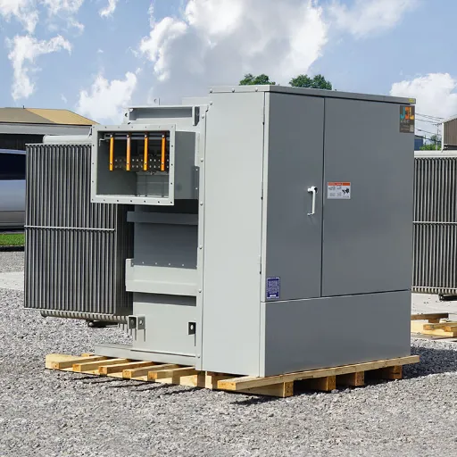
A pad-mounted transformer is an electrical distribution transformer that is situated on the ground and encased in a robust, tamper-resistant steel cabinet that is anchored to a concrete pad. These transformers are crucial interfaces between underground medium voltage (MV) distribution networks and low-voltage (LV) systems. There is generally a substantial step-down in voltage from 5 to 35 kV down to 120/240V or 277/480V for residential, commercial, and industrial applications.
Pad mount transformers are fully enclosed, unlike pole transformers that dangle from utility poles. This aesthetic, clean-line design eliminates any danger to the public, with a solid steel cabinet that has three-point latching systems in accordance with IEEE C57.12. 28, which will prevent access or protect all energized parts from unauthorized access and environmental exposure. Among installations that pad mount transformers are particularly well suited for are residential areas, commercial developments, and any site solely for public safety and aesthetic integration.
Key Components and Construction
Every pad mount transformer contains three essential functional elements within its weatherproof enclosure:
High-Voltage Terminations
- Bushings or bushing wells for underground cable connections
- Load-break switches for sectionalizing
- Bay-O-Net fuses or expulsion fuses for protection
- Surge arresters for overvoltage protection
Transformer Core and Windings
- Oil-immersed or dry-type core and coil assembly
- Step-down voltage transformation (e.g., 13.8 kV to 480/277V)
- On-load or off-load tap changers for voltage regulation
- Temperature monitoring and protection systems
Low-Voltage Distribution
- Air terminals or bus duct connections
- Circuit breaker or fuse protection
- Grounding provisions and neutral connections
Pad Mount vs. Pole Mount vs. Substation Transformers
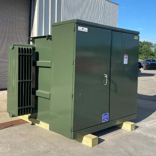
Understanding the distinctions between transformer installation types ensures you specify the right solution for your application. Each approach offers distinct advantages depending on capacity requirements, installation environment, and safety considerations.
Comparison Overview
| Feature | Pad Mount Transformer | Pole Mounted Transformer | Substation Transformer |
|---|---|---|---|
| Capacity Range | 5 kVA to 10,000 kVA | 10 kVA to 167 kVA | 1 MVA to 500+ MVA |
| Installation | Ground level on a concrete pad | Mounted on utility poles | Building or fenced yard |
| Voltage Range | Up to 46 kV primary | Up to 35 kV primary | Up to 765 kV primary |
| Safety Level | High (tamper-proof enclosure) | Medium (exposed, height protected) | High (controlled access) |
| Best For | Underground distribution, public areas | Rural overhead lines, low capacity | Bulk power, high capacity |
| Aesthetics | Low profile, landscaping compatible | Visible infrastructure | Requires screening/fencing |
| Cost (per kVA) | $25-70/kVA | $15-25/kVA | Variable, infrastructure-intensive |
When to Choose Each Solution
Pad Mount Transformers excel when you need:
- Underground cable distribution in residential or commercial areas
- Public safety with tamper-resistant enclosures
- Capacities between 100 kVA and 5,000 kVA
- Aesthetic integration without fencing requirements
- Rapid installation without extensive civil works
Pole-mounted transformers suit scenarios requiring:
- Overhead line distribution in rural or suburban areas
- Lower capacity requirements (under 100 kVA)
- Minimal ground footprint
- Cost-effective solutions where aesthetics are not critical
- Quick replacement without pad preparation
Substation Transformers remain optimal for:
- High-capacity bulk power transformation (over 5 MVA)
- Complex switching and protection schemes
- Transmission-level voltage conversion
- Permanent infrastructure with dedicated maintenance access
- Utility-scale generation interconnection
Real-World Selection Example
Let’s imagine that there was a huge retail developer who had a plan to build approximately 500,000 square feet shopping center to serve the suburb of a municipality. The municipality had an ordinance that stated not to have any overhead power lines. The developer took the time to evaluate three options:
Option A was to position the transformer on poles at the edge of the property. This violates the zoning requirement. There would be a significant overhead line to bring the service over the top of the property.
Option B was to construct a purpose-built substation. This took six months for the permit and construction, and real estate was needed for the secured substation yard.
Option C had pad mount transformers of which three, each having the same size of 1,500 kVA, were to be placed at strategic points in the property. These steps off on the underground utility cables, need a concrete pad, and are in place within four weeks. This fulfilled the zoning requirement, as well as allowing the development to operate on schedule.
Dead Front vs. Live Front Design
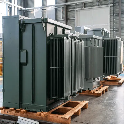
The choice between dead front and live front configurations represents one of the most important safety decisions in pad mount transformer specification. This design difference affects installation procedures, maintenance protocols, and regulatory compliance.
Dead Front Design (80% of Market)
Construction Features:
Dead front transformers feature fully enclosed energized components within grounded metal compartments. No live parts are exposed when the cabinet door opens. High-voltage connections use separable insulated connector systems complying with IEEE 386, including bushing wells and elbow connectors rated for 200A loadbreak or 600A/900A deadbreak operation.
Safety Advantages:
- No current-carrying parts exposed to operators
- Reduced arc flash risk during maintenance
- Compatible with hot-line tools for energized operation
- Viewing windows allow switch position verification without opening compartments
Applications:
Dead front designs are mandated or preferred for any installation with public access, including residential neighborhoods, parks, schools, and commercial pedestrian areas. Modern utility specifications increasingly require dead front configurations for all new underground distribution.
Live Front Design
Construction Features:
Live front transformers feature exposed, energized components visible when the cabinet door opens. High-voltage connections use porcelain bushings or spiral-style insulators with one-piece connectors and spade terminal blocks. Air serves as the primary insulation medium.
Characteristics:
- Lower upfront cost (15-25% less than dead front)
- Exposed bushings require careful handling
- Must be de-energized before servicing
- Legacy systems still common in industrial applications
Applications:
Live front designs suit remote industrial sites, utility substations, and controlled environments where only trained personnel perform maintenance and public access is restricted.
Design Decision Matrix
| Factor | Dead Front | Live Front |
|---|---|---|
| Public Safety | Superior (enclosed) | Acceptable (controlled access) |
| Maintenance Access | Safer, energized work possible | Requires de-energization |
| Initial Cost | Higher (+15-25%) | Lower |
| IEEE Compliance | Preferred by C57.12.34 | Legacy standard |
| Market Share | 80% of new installations | 20% (declining) |
Technical Specifications and Standards
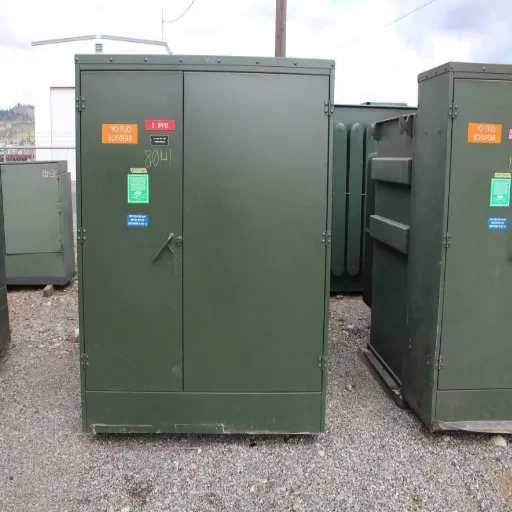
Pad mount transformers must comply with rigorous industry standards to ensure safety, reliability, and interoperability across electrical systems. Understanding these specifications helps engineers select appropriate equipment for their applications.
kVA Ratings and Capacity
Single-Phase Devices:
- Range: 5 kVA to 500 kVA
- Common sizes: 25, 50, 75, 100, 150, 167, and 250 kVA
- Application of utility: residential streets, small commercial consumers, or rural distribution
Three-Phase Devices:
- Range: 45 kVA to 10,000 kVA (10 MVA)
- Commercial sizes: 300, 500, 750, 1,000, 1,500, 2,000
- Industrial sizes: 2,500, 3,000, 3,750, 5,000 kVA
- Utility-scale: Up to 10,000 kVA
Sizing Best Practice: It’s recommended sizing guideline to work around 70-85% of the transformer’s nominal rating for optimal efficiency and durability, and always reserve a20-30% capacity in anticipation of any load expected to grow in frequency.
Voltage Configurations
Higher primary (High Voltage):
- Standard range: Up to 46 kV
- Normal distribution voltages: 4.16 kV, 12.47 kV, 13.2 kV, 13.8 kV, 14.4 kV, 24.94 kV, 25 kV, 34.5 kV
- Dual voltage option: 12.47/7.2 kV, 24.94/14.4 kV, 34.5/19.9 kV
Secondary (Low Voltage):
- Residential: 120/240 (single-phase) or 208Y/120V (three-phase)
- Commercial/Industrial: 480Y/277 V; 4160 V
- High voltage levels: Up to 600 V
Basic Insulation Level (BIL):
- 12 kV class: 95 kV BIL
- 25 kV class: 150 kV BIL
- 35 kV class: 200 kV BIL
IEEE and Industry Standards
IEEE C57.12.28 – Enclosure Integrity:
The tamper resisting shall consist of three-point latching door systems with tamper-resistant and security bolts used in conjunction with weather protection standards, securing the space by allowing unexceptional access.
IEEE C57.12.34 – Three-Phase Compartmental Type:
These particulars will define the space needed between the bushing mounting holes, height, and termination compartment dimensions in a standard three-phase pad-mount design, and how to do it in a proper way with respect to straight-line elbow connections, of which two may be lacking.
IEEE C57.12.38 – Single-Phase Standards:
It goes without saying that if the equipment isn’t needed, it has too many special requirements for the cold compounds and testing, which usually require smaller sizes or lighter weights.
IEEE C57.12.00 – General Requirements:
Performance expectations were broadened: temperature rise limits (90 degrees Celsius) are generally considered, definitions of rating-to-rating, efficiencies, sound levels, part-load values, and performance at selected temperature rise, duty classification, type tests, witness tests, and special tests are included in the scope.
Additional Standards:
- DOE 2016 Efficiency Regulations: These require minimum efficiency for each distribution transformer in the North American marketplace
- ANSI C57.12.20 & C57.12.38: Complementary standards for application-specific types
- CSA C227.3: Canadian standard for single and three-phase
- UL Listing: You always need this certification when you do an installation in North America.
- IEC 60076: International Standard for global markets outside America.
Loop Feed vs. Radial Feed
Loop Feed Configuration:
- Six high-voltage bushings (three-phase)
- Dual primary connections for network reliability
- If one cable fails, the other maintains service
- Essential for critical applications (hospitals, data centers)
- Higher cost but superior reliability
Radial Feed Configuration:
- Three high-voltage bushings (three-phase)
- Single primary connection
- Simpler and more economical
- Suitable for standard residential and commercial applications
- Typical for non-critical loads with acceptable outage risk
Applications and Use Cases
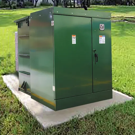
Pad mount transformers serve diverse applications where underground distribution, public safety, or aesthetic integration proves critical. Understanding these use cases helps specify appropriate features and configurations.
Residential Underground Distribution
Application: Present-day residential subdivisions and urban infill projects are increasingly requiring underground power distribution for aesthetic and reliability reasons. Earlier, the method of delivering power to homes with no overhead lines was to use Pad mount transformers strategically in these developments.
Typical Specifications:
- Single-phase: 25-100 kVA per unit
- Primary: 13.8 kV or 24.9 kV
- Secondary: 120/240V
- Dead front design for public safety
- Low-profile enclosures compatible with landscaping
Key Considerations:
- Noise levels (specify <50 dB for residential areas)
- Clearances from structures (generally 10 feet minimum)
- Vegetation management around enclosures
- Load growth planning for electric vehicle charging
Commercial Complexes and Shopping Centers
Application: Large retail developments, office parks, and mixed-use projects require substantial three-phase power with high reliability. Multiple pad mount transformers distributed throughout the property provide localized distribution with redundancy.
Typical Specifications:
- Three-phase: 1,000-2,500 kVA per unit
- Primary: 13.8 kV or 34.5 kV
- Secondary: 480Y/277V
- Loop feed configuration for reliability
- Stainless steel cabinets for corrosion resistance
Key Considerations:
- Peak demand calculations, including HVAC loads
- Future expansion capacity for tenant improvements
- Coordination with fire suppression systems
- Accessibility for maintenance without disrupting operations
Solar Farm and Renewable Energy
Application: Transformer pad mount used in a utility-scale solar installation on the collection side, stepping up the voltage of the inverter output (usually 480 V) to medium voltage (12-34 kV) for grid interconnection. Bidirectional power flow allows for battery storage integration.
Typical Specifications:
- Three-phase, 1,500-5,000 kVA.
- Step up: 0.48/12.47 kV or 0.69/34.5 kV.
- Loop feed for reliability
- High impedance for fault current limitation
- Temperature range extension for desert applications
Key Considerations:
- Harmonic filtration for the inverter-generated distortion
- Oversized capacity compared to intermittent loading cycles
- Desert-rated enclosures with extra cooling
- Compliant for rapid shutdown, NEC Article 690
Data Centers and Critical Infrastructure
Application: Pad mount transformers are used by hyperscale data centers. It enables a rapid expansion of power capacity, further increasing the capacity without having to commission and build separate substations. It is generally designed with an N+1 or 2N redundant configuration that benefits the continuous operation of the system during maintenance or failure.
Typical Specifications:
- Three-phase: 2,500 kVA-5,000 kVA per unit
- Primary: 13.8kV and 34.5kV
- Secondary: 480Y/277V
- Low-loss design for efficiency
- Digital monitoring for predictive maintenance
Key Considerations:
- Reliability requirements (99.999% uptime targets)
- FTS coordinating with UPS Systems
- Fire-resistance fluid options (natural ester)
- Remote monitoring integration with the building management system.
Electric Vehicle Charging Infrastructure
Application: Large-scale EV charging hubs for fleet depots and highway corridors require medium-voltage step-down to support multiple fast chargers. Pad mount transformers provide 1-6 MW capacity with rapid deployment to support charging network expansion.
Typical Specifications:
- Three-phase: 1,000-3,000 kVA
- Primary: 13.8 kV or 33 kV
- Secondary: 480Y/277V
- Dynamic load management capability
- High short-circuit withstand ratings
Key Considerations:
- Load diversity factors for simultaneous charging
- Power quality for sensitive charger electronics
- Expansion capacity for future charger additions
- Utility interconnection requirements
Selection Criteria and Buyer’s Guide
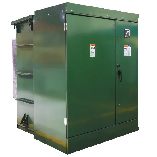
Because electricity requirement analysis, environmental influence, and life-story concerns play essential considerations in the selection of pad mount transformers, such a framework is the surest guarantee of really involving equipment.
Step 1: Determine kVA Requirements
Formulas for Calculating Loads:
kVA = Total Connected Load (kW) / Power Factor
Power Factor of Buildings:
- Residential: 0.85~0.90
- Commercial: 0.80~0.90
- Industrial: 0.70~0.85
Sizing Best Practices:
- Calculate the total connected load, including (20-30% future growth margin)
- Apply diversity factors to calculate non-coincident load
- Pick the kVA rating from the manufacturer’s standard table
- Between 70-85% of the rated capacity, the working range will be efficient
Example Calculation:
A commercial building has a total connected load of 800 kW with a 0.85 power factor. The minimum transformer size would be:
800 kW / 0.85 = 941 kVA
With a 25% future growth margin: 941 x 1.25 = 1,176 kVA, take the standard 1,500-KVA unit.
Step 2: Specify Voltage Configuration
Primary Voltage:
Match the utility distribution voltage. Common options:
- 12.47 kV (most common in North America)
- 13.8 kV (commercial/industrial standard)
- 24.9 kV (rural and utility applications)
- 34.5 kV (large commercial, solar farms)
Specify dual voltage if utility voltage may change or for inventory flexibility.
Secondary Voltage:
Match load requirements:
- 120/240V: Residential single-phase
- 208Y/120V: Commercial three-phase (older buildings)
- 480Y/277V: Commercial/industrial three-phase (modern standard)
- 4160V: Industrial motor loads
Step 3: Choose Insulation and Cooling
Oil-Immersed (Mineral Oil):
- Standard for outdoor installations
- Superior cooling and overload capacity
- Lower cost than alternatives
- Requires oil containment for environmental protection
- 25-30 year service life
Oil-Immersed (Natural Ester/FR3):
- Biodegradable and less flammable than mineral oil
- Higher fire point (300°C vs. 160°C)
- Extended transformer life (35-40 years)
- 10-15% cost premium
- Preferred for environmentally sensitive areas
Dry-Type:
- No flammable liquid (fire safety advantage)
- Preferred for indoor installations
- Higher initial cost for equivalent ratings
- Lower overload capacity
- Reduced maintenance requirements
Step 4: Select Feed Configuration
Choose Loop Feed When:
- Critical loads cannot tolerate outages
- Redundant cable paths available
- Higher reliability justifies additional cost
- Applications: hospitals, data centers, emergency services
Choose Radial Feed When:
- Standard reliability is acceptable
- Single cable source
- Cost optimization is a priority
- Applications: residential, standard commercial
Step 5: Specify Enclosure and Options
Material Selection:
- Galvanized Steel: Outstanding price and standards,
- 304 Stainless Steel: Corrosion resistance along coastal/marine
- 316 Stainless Steel: Harsh environments for maximum corrosion resistance
Essential Options:
- Pressure relief device
- Liquid level gauge
- Temperature gauge
- Tap changer (±2.5% or ±5% for voltage adjustment)
- Surge arresters
Advanced Options:
- Digital temperature monitoring
- Remote monitoring sensors
- Oil containment systems
- Acoustic enclosures for noise-sensitive areas
Cost Analysis and Pricing
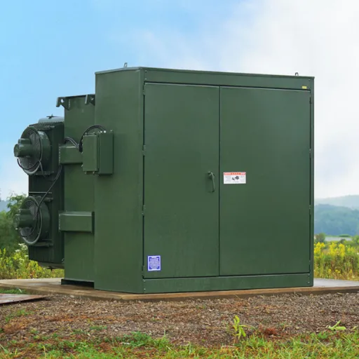
Understanding the total cost of ownership for pad mount transformers helps build accurate project budgets and evaluate lifecycle economics. While unit prices vary significantly based on specifications, several general principles apply.
Unit Price Ranges (2025)
| kVA Rating | Single-Phase | Three-Phase | Typical Applications |
|---|---|---|---|
| 25-75 | $2,000-4,000 | $4,000-7,000 | Residential |
| 100-300 | $5,000-8,000 | $10,000-18,000 | Small commercial |
| 500-1,000 | N/A | $25,000-45,000 | Commercial/Industrial |
| 1,500-2,500 | N/A | $50,000-85,000 | Large commercial |
| 3,000-5,000 | N/A | $100,000-180,000 | Industrial/Utility |
Price per kVA: $25-70/kVA typical, with larger units achieving lower per-kVA costs.
Factors Affecting Cost
Capacity: Cost scales not linearly with kVA, as 2000 kVA costs less than twice as much as 1,000 kVA due to manufacturing efficiency.
Voltage Class: Higher primary voltages increase insulation requirements and cost more (34.5 Kv means 13.8 Kv), but it may be 10-20% more.
Features and Options:
- Dead front vs. live front: +15-25% in comparison to live-front technologies
- Ester fluid: +10-15% for natural ester
- Loop feed vs. radial: +10-20% for loop feed
- Stainless steel enclosure: +20-30% in comparison to fiberglass
- Digital monitoring: +5-10% at the top end
Certifications: UL-listed units cost an increase of 15-25% for domestic products, mainly because of the certification and testing requirements.
Installation Costs
Site Preparation:
- Concrete pad: $2,000, up to $5,000 depending on size and soil conditions.
- Excavation and backfill: $1,000 up to $3,000.
- Grounding system: $500 through $1,500.
Electric Connection:
- Termination: $2,000 up to $5,000 for high-voltage cables.
- Distribution: $1,000 up to $3,000 for low-voltage.
- Protection and metering: $1,500 through $4,000.
Total Installation: This is usually between thirty and fifty percent of the cost of the equipment for a typical installation.
Lifecycle Cost Considerations
Efficiency in operation:
The 2016 standard efficiency of DOE, demanding the least efficiency from units that vary from 98.5% (small units) to 99.2% (large units), says that a 1% efficiency difference over 25 years on a 1,000 kVA transformer at 75% of its load would represent $15,000-25,000 in energy costs.
Maintenance:
- Routine checks: $200-500/year
- Oil testing and analysis: $300-800 every 2-3 years
- Major maintenance (bushing replacement, etc.): $2,000-5,000 through life
Service Life:
- Mineral oil units: 25-30 years
- Natural ester units: 35-40 years
- Dry-type units: 20-30 years
Installation Requirements and Best Practices
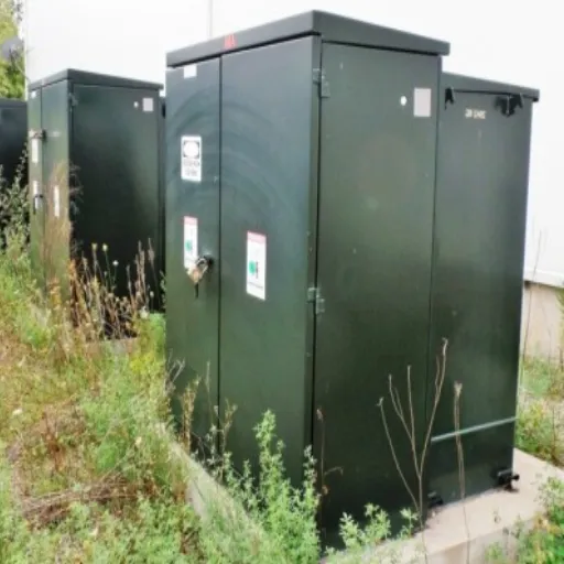
Proper installation ensures safe operation, regulatory compliance, and optimal transformer performance. Following established guidelines prevents costly corrections and safety hazards.
Site Selection Criteria
Clearances (per IEEE and NEC requirements):
- Front (access door): 10 feet minimum for maintenance access
- Sides and rear: 3 feet minimum
- From combustible structures: 10 feet minimum
- From doors/windows: 5 feet minimum
- From property lines: Verify local requirements (typically 3-5 feet)
Elevation and Drainage:
- Install above the base flood elevation in flood-prone areas
- Ensure positive drainage away from the pad
- Avoid low spots where water can accumulate
- Consider snow accumulation in northern climates
Accessibility:
- Maintain a clear path for maintenance vehicles
- Ensure crane or boom truck access for replacement
- Coordinate with landscaping to prevent root intrusion
Concrete Pad Specifications
Dimensions:
- The pad should extend 6 to 12 inches beyond the transformer on all sides
- Usual thickness: 12-18 inches
- Reinforced with #4 rebar on 12-inch centers
Construction:
- Should result in a minimum of 3,000 psi concrete
- Minimum 1/4-inch level tolerance
- Add grounding electrode encasement
- Should slope the top surface away from the transformer for proper runoff
Types of Foundations:
- Standard Pad: Reinforced concrete over compacted base
- Pier Foundation: Elevated piers in poor soil conditions
- Vault Installation: Design below grade for severe space conflicts.
Electrical Connection Guidelines
Voltage Availability:
- Use a 15 kV soft cable to the highest level of 12.47 kV
- Use a 25 kV soft cable to the highest level of 24.9 kV
- Use a 35 kV soft cable to the highest level of 34.5 kV
- Place tight stress cones correctly.
- Connect to too much torque according to the manufacturer’s specifications
Low-Voltage Connections:
- Size conductors to be in accordance with the NEC’s applicable tables of ampacity
- Use the listed lugs and connectors
- Maintain the phase sequence consistency
- Install proper grounding and bonding
Protection and Metering:
- Coordinate or handle over-current protection with utility needs
- Attach current transformers for metering if needed
- Connect the terminals with a surge protector.
Testing and Commissioning
Pre-Energization Tests:
- Insulation resistance (megger) testing
- Winding resistance measurements
- Turns ratio verification
- Tap changer operation check
Energization Sequence:
- Energize the primary side first
- Verify secondary voltage and phase rotation
- Load gradually, monitoring temperature
- Record baseline readings for future comparison
Maintenance and Lifecycle Management
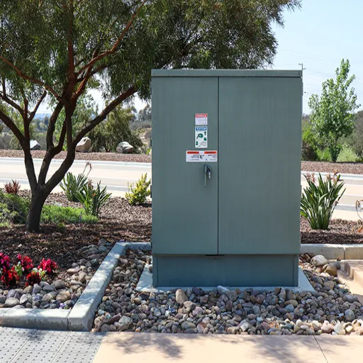
Proper maintenance extends transformer life, prevents failures, and ensures reliable operation. A structured maintenance program protects your investment and avoids costly emergency repairs.
Routine Inspections (Quarterly)
Visual Inspection:
- Look for oil leaks around bushings, valves, and gaskets
- Inspect the enclosure that might be corroded, damaged, or tampered with
- Ensure the proper function of door latches and locks
- Remove vegetation and debris around the equipment
- Check for abnormal sounds such as those of arcing, buzzing, and rattling
Indicator Checks:
- Record liquid level gauge reading
- Verify pressure/vacuum gauge within normal range
- Check temperature gauge (if ambient, should match air temperature)
- Inspect desiccant breather condition (if equipped)
Periodic Maintenance (Annual)
Electrical Testing:
- Infrared thermography of connections (hot spots indicate problems)
- Inspect and torque bolted electrical connections
- Test the operation of switches and protective devices
- Verify grounding system integrity
Mechanical Inspection:
- Exercise switches and tap changers
- Inspect the gasket condition and replace if deteriorated
- Check paint and touch up corrosion spots
- Verify nameplates and warning labels are legible
Advanced Diagnostics (Every 3-5 Years)
Oil Analysis (Oil-Immersed Units):
- Dissolved gas analysis (DGA) detects internal faults
- Moisture content testing
- Dielectric strength testing
- PCB screening (for older units)
Electrical Testing:
- Power factor testing of insulation
- Winding resistance trending
- Turns ratio verification
- Excitation current testing
Common Failure Modes and Prevention
Insulation Deterioration:
- Cause: Thermal aging, moisture, oxidation
- Prevention: Oil testing, maintain loading within ratings, temperature monitoring
Bushing Failures:
- Cause: Tracking, contamination, mechanical damage
- Prevention: Regular cleaning, infrared scanning, and inspection
Problems with Tap Changers:
- Cause: Mechanical wear, trouble from contact burning
- Prevention: Regular operation, contact replacement, inspection
Overloading:
- Cause: Load growth beyond original design
- Prevention: Load monitoring, thermal modeling, planned upgrades
Expected Service Life
With proper maintenance:
- Mineral oil units: 25-30 years
- Natural ester units: 35-40 years
- Dry-type units: 20-30 years
End-of-life typically determined by:
- Insulation condition (power factor, oil tests)
- Core and winding condition
- Economic comparison of repair vs. replacement
- Efficiency compared to modern standards
Leading Manufacturers and Selection
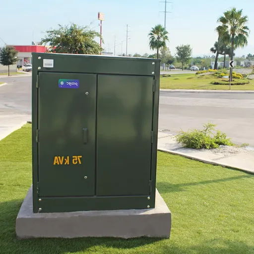
Selecting a reliable supplier ensures quality construction, compliance with set standards, and continuing support from the supplier. The global pad mount transformer market features both multinational corporations and specialist regional manufacturers.
Global Market Leaders
ABB (21% Market Share)
- Global leader with a comprehensive product range
- Strong R&D and smart grid integration
- Premium pricing with an extensive service network
- Focus on digital monitoring and predictive maintenance
Schneider Electric (18% Market Share)
- Integrated energy management solutions
- Strong presence in commercial and industrial segments
- EcoStruxure platform for digital services
- Emphasis on sustainability and efficiency
Eaton Corporation
- Significant North American presence
- $340 million US investment in 2025 for capacity expansion
- Strong utility relationships
- Comprehensive power system expertise
Siemens Energy
- Leading transmission and distribution portfolio
- Advanced monitoring and diagnostics
- Strong in utility-scale applications
- Global service network
Regional Specialists
ERMCO (Dyersburg, Tennessee)
- North American leader in distribution transformers
- Strong utility market presence
- Extensive dead front product line
- Responsive lead times for standard designs
Prolec GE (Joint Venture)
- Significant North American manufacturing
- GE technology and quality standards
- Comprehensive pad mount offerings
- Strong in renewable energy applications
Virginia Transformer
- US-based manufacturer
- Custom and specialty transformer focus
- Rapid delivery capabilities
- Strong technical support
Chinese Manufacturers for Export
Chinese manufacturing firms, like Shandong Electric, offer unique advantages for global markets:
Cost-Effectiveness:
The scale of manufacturing and integrated supply chain saves 20-30 percent of cost in comparison with Western manufacturers without affecting the quality of the product, which facilitates optimizing budgets or expanding capacities within capex-constrained plans.
Customization Flexibility:
Chinese firms are normally more proficient at handling non-standard designs, out-of-the-ordinary voltage ratios, and specialist application designs. Flexibility of this form can also prove extremely useful for smaller projects meeting specific requirements.
Rapid Production Cycles:
Unlike Western providers that take roughly 16-24 weeks to complete the job, companies based in China can deliver custom-designed products in as little as 8-12 weeks. Integrated manufacturing and material sourcing also shorten the lead times, even further suited to today’s tight project schedules.
Multi-Standard Compliance:
All the established manufacturers in exports have an uncomplicated, comprehensive catalog that has certifications for IEEE, IEC, and regional standards at the same time, to be able to enhance overseas procurement through a single source.
Export Experience:
Mature delivery strategies and packaging expertise reduce all paper requirements in shipping while extending the entire shipment into different parts of the world.
Looking for a reliable pad mount transformer manufacturer with global export experience? Contact Shandong Electric to discuss your project.
Conclusion
Pad mount transformers are the best option for underground power supply for the reasons associated with safety, aesthetics and reliability. These static units have the capability and efficiency of the conventional distribution transformers but avoid the visual impact and public safety concerns associated with open overhead equipment.
Utility engineers completing designs for underground residential areas, commercial developers, or renewable energy system designers using solar farms, are trying to complete a pad mount transformers delay solution that has years of application. Dead front or live front, loop feed or radial, and different insulation kinds are available for specific applications.
The worldwide tendency of consumers, utilities, and governments alike to demand that utilities ‘downgrade’ their visible systems increases the use of pad mount transformers as utilities approach the underground or undergrounded distribution system. This effect has increased the market for these devices and was worth $6.8 billion as of 2025, emphasizing their importance for contemporary grids.
Key Takeaways
- Safety First: The standard of dead fronts insulation with energized parts fully enclosed within the gear has been adopted by 8 out of every 10 customers requesting this type of insulated equipment because it enhances public safety.
- Capacity Flexibility: A range of standard pad mount transformers is available for utilities to order from as small as 25 kVA residential transformers to as large as 10000 kVA industrial transformers.
- Standards Compliance: Lighting and distribution transformers meet the requirements of applicable standards, including IEEE C57.12. 28, C57.12. 34 and DOE efficiency 2016.
- Lifecycle Economics: Pad mount transformers can achieve a service life of 25-40 years without the need for intensive maintenance, leading to a competitive total cost of ownership.
- Application Versatility: Pad Mount Transformers allow the distribution of electricity to various needs, from housing estates, solar farms, and data centers.
Next Steps
For utility engineers developing underground distribution specifications, commercial developers planning project power infrastructure, or renewable energy projects requiring grid interconnection, the next step is engaging with experienced manufacturers who understand your specific application requirements.
Contact Shandong Electric for a technical consultation on your pad mount transformer project. Our engineering team provides detailed specifications, cost estimates, and application guidance tailored to your kVA requirements, voltage needs, and installation environment.
Frequently Asked Questions
What clearance should be left around the transformer?
The NEC and also the IEEE standards establish the minimum clearances needed for fire safety and functional access. For the front access door, ten feet of clearance is required, whereas the sides and the back should be kept at least eight feet away from the wall. Combustible materials, and there should be at least 5 feet between the transformer and building egress points. Refer to the local amendments regarding these universal codes before concluding.
How long is the life expectancy or durability of pad mount transformers?
Under proper conditions of use, these Pad Mount Transformers have a 15-30 year lifespan with regular checking of oil containing mineral oil. The history of dry ethylene, which is being utilized in Dry Type Transformer, increases the longevity of the foam, thus the expectancy increases by 10 more years than all other equivalents. It should further be pointed out that dry-type transformers have a lifespan of about 20 – 30 years to activity. Regular check-ups and maintenance of the camping transformers are recommended to increase the transformers’ lifespan.
What is the difference between dead front and live front transformers?
Dead front transformers feature fully enclosed energized components with no exposed live parts when the door opens, using insulated IEEE 386 elbow connectors. Live front designs expose porcelain bushings and connections when accessed. Dead front configurations offer superior safety for public areas and have become the industry standard, representing 80% of new installations.
How do I calculate the right kVA size for my application?
Calculate total connected load in kW, divide by power factor (typically 0.80-0.90 for commercial), then add 20-30% for future growth. Size the transformer to operate at 70-85% of rated capacity for optimal efficiency. For example, an 800 kW load at 0.85 power factor requires 941 kVA; with growth margin, select a 1,500 kVA unit.
Could I use a pad mount transformer in a solar power installation?
Yes, pad mount transformers are often used for this purpose, providing voltage transformation from inverters’ consolidation voltage (48 0-690 V) to a given network voltage (12 kV – 34 kV) for utility-scale installations. These transformers may have the capability for reversible operation, be adaptable to the specified harmonics, and offer suitable impedance.
What is the maintenance level of pad mount transformers?
The level of maintenance of pad mount transformers is generally lower compared to other types of electrical equipment. The routine inspections take place every three months to check leaks, the state of the enclosure, and read indicators. Battery checks, where infrared checks the connections is carried out in annual inspections. Construction oils are recommended for usage after every 3-5 years without the purchase of a new one. The routine maintenance cost is usually $500 to 1000 every year.
Are pad mount transformers more expensive than pole-mounted units?
Initial unit cost runs 30-50% higher than equivalent pole-mounted transformers, ranging 25−70/kVAversus25−70/kVAversus15-25/kVA. However, pad mount installations eliminate pole costs, reduce line construction, and require no fencing. For underground distribution applications, total installed costs prove competitive while delivering superior safety and aesthetics.
Ready to specify a pad mount transformer for your underground distribution project? Contact Shandong Electric Co., Ltd. for expert engineering support, custom specifications, and competitive quotations tailored to your project requirements.