Transformer Troubleshooting: A Complete Guide to Fault Diagnosis and Solutions
The manufacturing facility experiences an hour of lost production, which costs between 22000 and 260000, because of an unplanned transformer failure. Most of those failures were preventable. The CIGRE Working Group research surveyed more than 22000 transformers that exist in 20 different countries and discovered that faults develop through a gradual process, which releases detectable warning signs that appear before catastrophic failure. The system must assess the value of these signs while it creates a complete response strategy.
You already understand that transformers are critical infrastructure. The undetected fault, which remains inactive for several weeks, will endanger equipment and operational processes and the security of your facility and its economic stability. The good news transformer fault patterns are predictable, and the right diagnostic approach will enable you to detect most problems before they become critical issues.
The guide provides a structured transformer troubleshooting framework for maintenance engineers and technical managers, which includes common fault types and diagnostic methods and both oil-immersed and dry-type unit procedures and maintenance checklists, and a decision framework for repair and replacement.
Why Transformer Faults Happen
Transformers have a service life of several decades, yet they function under constant electrical, thermal, and mechanical pressures. The first step in an effective transformer troubleshooting program requires technicians to identify the specific locations where faults develop.
Common Root Causes of Transformer Failure
The IEEE and CIGRE survey data, which they gathered from transformer systems worldwide, show that transformer failures occur because of a limited number of components.
- Windings: Account for 25 to 40% of all transformer failures. The main causes of failures are turn-to-turn insulation breakdown and conductor overheating, together with short circuits that occur when through-fault currents pass through the system.
- On-load tap changers (OLTCs): Also responsible for 25 to 40% of service events. The system experiences typical failures through contact wear and oil contamination in the tap changer compartment and drive mechanism failures.
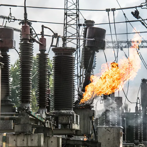
- Bushings: Contribute to 10 to 25% of failures and are implicated in approximately 70% of transformer fires. The main causes of failures in aged bushings come from moisture ingress and surface tracking, together with partial discharge.
- Core: Core faults occur with low frequency at 5 to 10%, but they create serious issues that require special attention because they cause inter-lamination short circuits that result in increased no-load losses and gradual overheating.
Systemic factors that exist beyond specific component failures create higher fault risk across all types of system malfunctions. The moisture ingress problem leads to insulation system failures, which account for 90 percent of distribution transformer breakdowns in areas with high humidity. The Montsinger Rule states that for each 10-degree Celsius increase in temperature above rated limits, insulation life decreases by half. Overloading beyond nameplate rating accelerates insulation aging exponentially because the Montsinger Rule states that for every 10-degree Celsius rise in operating temperature above rated limits, transformer insulation life is halved.
The Cost of Ignoring Early Warning Signs
The steel processing facility in Shandong Province experienced an incident that needs examination. Maintenance staff observed a slow temperature increase, which caused the winding thermometer to show a temperature of 78 degrees Celsius after four months from its initial reading of 65 degrees Celsius. The team documented their findings, yet they did not pursue any further examination. The team did not conduct any dissolved gas analysis testing. The team did not plan any inspections for the cooling system.
The system experienced a sudden shutdown because of an internal winding fault, which occurred six months after the initial breakdown. The transformer remained offline for 23 days because the team needed to find and install a replacement unit. The production losses surpassed the cost of the replacement transformer by three times its purchase price.
The first signals of trouble appear through diagnostic data. Transformer research requires engineers to treat these findings as operational signals that they need to address through systematic methods.
The [transformer maintenance best practices guide] provides inspection intervals and condition assessment protocols, which create a foundation for proactive maintenance.
Common Transformer Problems and Symptoms
Systematic transformer troubleshooting starts with accurate symptom recognition. The first diagnostic tests should be selected based on the particular failure mechanism that each symptom cluster demonstrates.
Overheating and Thermal Issues
The most frequent issues with power transformers stem from thermal problems that they experience. The top-oil temperature of oil-immersed units requires investigation when it exceeds 75 to 85 degrees Celsius above ambient temperature or when winding temperature indicators reach their trip limit.
The following factors probably caused the problem:
- The system experienced overloading, which exceeded its rated kVA capacity.
- The cooling system failed because its radiators became blocked, its cooling fans stopped working, and its oil level dropped.
- The system experienced high ambient temperature conditions, which need to be derated without any load present.
- Internal faults produced excessive heat through short circuiting of turns and core lamination faults.
- The system experienced limited oil flow because of blocked cooling channel pathways.
The initial troubleshooting process begins with these steps. The first step involves checking the load against the nameplate rating. The second step requires inspecting cooling radiators to identify debris and blocked fins. The third step involves checking if all forced cooling fans are currently functioning. The fourth step requires checking the oil level present in the conservator of oil-immersed units. The team should schedule infrared thermography and dissolved gas analysis after confirming that both load and cooling systems function properly. The tests should take place before the upcoming period of equipment operation.
Abnormal Noise and Vibration
The production of a low-level hum sounds normal to me. The core laminations experience vibrations at double the supply frequency because of magnetostriction, which produces 100 Hz vibrations in 50 Hz systems and 120 Hz vibrations in 60 Hz systems. This situation develops according to established patterns. The investigation requires previous sounds to maintain their original volume until new sounds emerge.
Warning sounds to investigate:
- Increased hum intensity: This situation generally shows that overexcitation occurs because operators apply voltage that exceeds the equipment’s rated capacity, or the core clamping hardware has begun to loosen.
- Crackling or intermittent discharge: This sound pattern shows that partial discharge occurs inside the tank, which represents a critical insulation fault that demands immediate investigation.
- Mechanical rattling: The system experiences this problem because of either loose internal components or broken cooling fan mounts or loose external hardware.
- Bubbling or gurgling (oil-immersed units): This sound indicates the presence of moisture in the oil or internal arcing, which creates gas pockets.
The investigation must examine all sound profile changes that lack an apparent explanation. The presence of partial discharge represents an essential discovery. You need to stop all operations when you detect crackling sounds together with a burning smell, and then you must contact experts for equipment inspection before proceeding with power restoration.
Oil Leaks and Contamination
Oil serves two functions in oil-immersed transformers because it acts as both their coolant and their main insulation material. Any loss of oil results in dual failures of both cooling and insulation functions. The dielectric strength of contaminated oil decreases at a fast rate.
Leakage occurs most frequently through the following points: Gaskets at the tank cover, radiator connection joints, bushing base seals, drain valve seats, and the OLTC compartment.
The following contamination indicators should be measured:
- Moisture content above 20 ppm (Karl Fischer titration method) signals elevated insulation risk
- The dielectric strength of the material falls below 30 kV according to the IEC 60156 test method, which demonstrates that it does not provide sufficient insulation properties.
- Oil color change from amber to dark brown or black indicates that thermal or oxidative breakdown has occurred.
The first step requires you to find the leak point and then block it. The full oil quality assessment should include measurements for moisture content and dielectric strength, acidity, interfacial tension and dissolved gas analysis. Oil that fails multiple parameters simultaneously typically requires filtration or replacement.
Voltage Irregularities and Load Issues
The voltage output shows problems because it produces results that differ from expected values and demonstrates instability during constant load testing.
Symptom-cause relationships:
- High secondary voltage, no OLTC adjustment made: Possible shorted turns in the primary winding, reducing the effective turns ratio
- Low secondary voltage under load: Incorrect tap position, overloading, or increased winding resistance from a loose connection or corroded terminal
- The voltage imbalance between phases exceeds 1 to 2% because of two factors, which include asymmetric loading and the open phase condition that exists on the primary side.
A turns ratio test (TTR) quickly confirms whether the actual winding ratio matches the nameplate specification. The test provides information about which parts of the system develop faults through its combination with a winding resistance measurement, which tests three areas: tap positions, windings and external connections.
Insulation Degradation
The insulation of transformers, which includes liquid oil and cellulose paper used in oil-immersed units, together with cast resin and varnish used in dry-type units, shows performance degradation when exposed to thermal, electrical and chemical stressors. The current state of insulation materials in transformers determines the time period until the transformers cease to function.
Indicators of degraded insulation:
- Insulation resistance (IR) below acceptable limits for the winding voltage class (compare against established baseline, not absolute values alone)
- Polarization index (PI) below 2.0, indicating moisture absorption or contamination in the insulation system
- Electrical and acoustic methods show increased partial discharge activity
- High furan content in transformer oil, confirming cellulose paper breakdown (oil-immersed units)
Engineers need to evaluate insulation problems because these issues affect whether a transformer can keep operating, needs special monitoring, or requires a complete shutdown.
Transformer Fault Diagnosis Methods
Identifying symptoms narrows the field of possible causes. Confirming the diagnosis requires selecting the right diagnostic technique for the fault type suspected.
Dissolved Gas Analysis (DGA): The Primary Diagnostic Method
Dissolved gas analysis (DGA) serves as the primary diagnostic instrument for solving problems in oil-filled transformers. The thermal or electrical stress on insulation and oil materials creates specific gases that dissolve into transformer oil. The process of gas analysis enables the determination of fault type and fault intensity.
Gas-to-fault interpretation table:
| Gas | Primary Fault Source | Fault Type Indicated |
|---|---|---|
| Hydrogen (H2) | Partial discharge, corona | Electrical discharge in oil or at insulation surfaces |
| Methane (CH4) | Low-temperature thermal fault | Overheating below 300 degrees C |
| Ethylene (C2H4) | High-temperature thermal fault | Severe overheating, 300 to 700 degrees C |
| Acetylene (C2H2) | High-energy electrical arcing | Arcing or severe discharge above 700 degrees C |
| Carbon monoxide (CO) | Paper insulation degradation | Cellulose thermal decomposition |
| Carbon dioxide (CO2) | Paper insulation aging | Normal aging if the CO2/CO ratio is above 3 |
| Ethane (C2H6) | Moderate thermal fault | Overheating at 150 to 300 degrees C |
Acetylene stands as the most critical discovery because its presence proves that arcing or high-energy discharge events occurred at the site. The Duval Triangle together with important gas ratio techniques, which IEC 60599 defines, provides a complete method for interpreting DGA results. The IEEE C57.104 standard establishes an equivalent assessment system which determines operational thresholds through specific gas measurements and total dissolved combustible gas (TDCG) assessment.
Sampling frequency: The required sampling frequency for standard service units needs to be conducted at its annual minimum point. The units with active DGA abnormalities should be tested either monthly or quarterly. The testing needs to be conducted after every through-fault event.
Infrared Thermography
The system requires no power shutdown to detect temperature differences on transformer outer surfaces through its thermal imaging technology. The system operates most efficiently when its load exceeds half of its maximum capacity.
What to look for:
- Investigators need to examine bushing hot spots that exceed 10 to 15 degrees Celsius above matching phase components and require immediate action when temperatures reach 40 degrees Celsius.
- The system experiences blocked flow channels, which manifest as uneven heating between its cooling radiator sections.
- The tank surface displays temperature differences that result from phase-to-phase thermal distribution.
- The OLTC compartment contains hot spots that show contact resistance buildup.
The infrared results need to be analyzed together with the load data, which was obtained during the scan, and compared against baseline scans that were conducted at equivalent load conditions.
Partial Discharge Monitoring
Partial discharge (PD) occurs when localized electrical stress exceeds the breakdown strength of an insulating material at a defect point, producing small discharges that do not immediately bridge the full insulation gap. The process of PD gradually destroys insulation material until complete breakdown occurs.
Detection methods available without outage:
- Acoustic emission sensors attached to the transformer tank detect ultrasonic signatures of PD
- High-frequency current transformers (HFCT) on bushing terminals or earth connections capture high-frequency PD pulses
- Ultra-high frequency (UHF) sensors for enclosed GIS-connected transformers
The engineering team needs to evaluate the remaining insulation life after persistent PD activity exceeds site thresholds above the established limits. DGA and PD monitoring work together in oil-immersed transformers because DGA shows total insulation deterioration, and PD monitoring shows current discharge points.
Electrical Testing: IR, TTR, and FRA
The three standard electrical tests determine quantitative data that shows different transformer health aspects.
- Insulation Resistance (IR) and Polarization Index (PI) testing uses DC voltage testing at three levels, which depend on the tested winding voltage class to measure leakage current. The results compare against the transformer’s established baseline, which needs temperature adjustments. The polarization index shows moisture presence or extreme contamination when its value drops below 2.0, according to the 10-minute reading divided by the 1-minute reading.
- Turns Ratio Test (TTR) assesses the actual winding ratio of transformers by testing their OLTC tap positions and comparing results to nameplate specifications. Deviations greater than 0.5% from nameplate specification indicate possible shorted turns, winding damage, or OLTC contact problems.
- Frequency Response Analysis (FRA) measures electrical frequency responses of windings and compares those responses to a reference fingerprint. The through-fault short-circuit forces and transport damage cause mechanical deformation of windings, which results in specific shifts of the FRA signature. The test becomes especially critical after instances when external short-circuit protection systems have been activated.
Troubleshooting Oil-Immersed Transformers
The diagnostic dataset from oil-immersed units exists as the most comprehensive dataset, which surpasses all transformer types because their insulating oil stores evidence of internal faults. Here is a structured approach to oil-immersed transformer troubleshooting.
Step-by-Step Diagnostic Process for Oil-Immersed Units
- The operational history requires assessment. The temperature records and load measurements, together with OLTC operation data and past DGA results, need to be retrieved. The study needs to determine which patterns show diagnostic value through their development across multiple months instead of their single-time measurements.
- The process begins with an outside visual examination. The inspection process requires the detection of oil leaks and oil stains. The conservator tank oil level needs confirmation. The Buchholz relay indicator requires examination to determine whether gas has built up. The pressure relief device needs examination to determine whether it has been used. The bushing assessment requires evaluation of its surface state and the oil level present in its oil-filled components.
- The process starts with dissolved gas analysis. DGA serves as the primary diagnostic method for transformers that operate with oil insulation, even when no faults exist. The portable on-site DGA instruments supply results to urgent situations within a time frame of several hours.
- The process needs to perform infrared thermography testing during active equipment operation. The process needs to detect external thermal abnormalities that exist at bushings and cable connections, and radiator headers.
- The electrical assessment needs to happen during the upcoming power outage. The team will execute insulation resistance, turns ratio and winding resistance tests. The team needs to add FRA testing to their report because a through-fault event has occurred or because DGA results indicate serious winding faults.
- All results need to be correlated. The single abnormal measurement provides a harmless explanation. Multiple findings pointing toward the same component confirm fault location.
Specific Oil-Immersed Fault Indicators
- The OLTC problems appear through three different indicators, which include increased mechanical noise from the tap changer during switching, rising winding resistance on the affected phase, and DGA results that show acetylene in the OLTC oil compartment. The OLTC oil compartment requires separate sampling from the main tank oil because this method enables identification of OLTC-specific gas generation.
- Bushing problems appear as thermal anomalies during infrared inspection and through bushing diagnostic testing, which shows elevated power factor or capacitance after C1/C2 measurements and through tracking that becomes visible on the porcelain surface. A bushing that displays both thermal and electrical anomalies needs replacement before the next energization occurs.
Our [oil-immersed transformer solutions] include technical documentation that contains transformer-specific baseline test values that support ongoing maintenance and troubleshooting efforts.
Troubleshooting Dry-Type Transformers

Dry-type transformer troubleshooting follows the same diagnostic logic but uses different indicators. Without oil, there is no DGA to rely on. These units depend on air circulation, cast resin, or varnish insulation.
Step-by-Step Diagnostic Process for Dry-Type Units
- The process requires visual inspection of windings to identify any signs of damage. The search should identify any signs of overheating through discoloration and any cracks that exist in resin encapsulation, any carbon tracking that affects insulation surfaces, and any physical damage that resulted from external forces. Dry-type units provide operators with better visual access to their components than oil-immersed units.
- The assessment requires checking all ventilation pathways. Dry-type transformers depend entirely on air circulation for their cooling needs. The system experiences rapid temperature increase because of blocked ventilation louvers and enclosure obstructions, and cooling fans have failed. The initial step during overheating investigations requires this process.
- The process requires measuring the temperatures of the windings. The system needs to use either built-in temperature sensors or infrared measurement equipment to perform measurements. The results need to be compared with the transformer’s insulation class limit, which states that Class B allows 130 degrees C maximum winding temperature, while Class F allows 155 degrees C, and Class H permits 180 degrees C.
- The process requires testing insulation resistance. The test needs to use a voltage that matches the winding rating. Dry-type units are more sensitive to surface contamination than oil-immersed units because industrial dust, moisture, and chemical vapors reduce surface insulation resistance and create tracking conditions.
- The system needs to perform testing for partial discharge. The acoustic emission sensors identify partial discharge activities in dry-type systems through their detection capabilities. The presence of discharge activity becomes audible through crackling sounds that occur inside the enclosure when the system operates.
- The system needs to conduct an inspection of connection torques and verify their accuracy. Maintenance personnel can access terminal connections of dry-type units during maintenance work. Loose connections, together with corroded connections, create heat that builds up in specific areas. The process requires all terminal hardware to receive the manufacturer’s recommended torque specifications.
Specific Dry-Type Fault Indicators
The operational risk from surface contamination to dry-type transformers increases when they operate in locations that have conductive dust and chemical vapor and experience condensation. The service life of equipment increases when operators perform routine cleaning on both the winding surfaces and the interior spaces of enclosures. The visible carbonized paths on insulation surfaces, which indicate damage, require permanent replacement of the affected area. The affected winding section needs replacement according to this requirement.
Our [dry-type transformer] contains the rated temperature class information, insulation system details, and testing standards that apply to our products.
Preventive Maintenance to Avoid Transformer Faults

The most cost-effective form of transformer troubleshooting is the kind that prevents faults from developing in the first place. A structured maintenance program detects developing problems early, when the range of intervention options is still wide, and costs are contained.
Routine Inspection Checklist
Monthly inspections (no outage required):
- The oil level needs to be checked through the conservator or the sight glass of oil-immersed units.
- The inspection should examine all oil leak points, including gaskets, bushing bases, and drain valves.
- The testing process needs to verify the operational status of installed forced cooling fans.
- The technician needs to listen for any signs of abnormal noise or vibration that show equipment problems.
- The system needs to record top-oil temperature together with ambient temperature, which will help track temperature development.
- The testing process needs to confirm that all alarm signals and protection signals can be heard without any obstruction.
Quarterly inspections:
- Clean all air vents and all air vent enclosure parts that belong to dry-type units.
- Inspect all bushing surfaces to find both contamination and any signs of electrical tracking.
- Inspect all ground connections and bonding connections to find any signs of corrosion.
- The technician must verify both the operation cycle counter and the oil level of the OLTC system if the system includes those functions.
- The testing schedule must include protective relay test dates, which require confirmation.
Annual testing:
- The analysis uses dissolved gases from the fresh oil sample, which comes from oil-immersed units.
- The complete oil quality assessment measures moisture content and dielectric strength, acidity, and interfacial tension.
- The procedure requires us to measure both insulation resistance and polarization index.
- The system conducts infrared thermography to evaluate its performance during regular operating conditions.
- The research tests the turns ratio by evaluating all operational load tap changer positions.
- The entire process requires us to measure winding resistance across all phases.
Every 3 to 5 years (or per condition assessment):
- Frequency response analysis (especially following any through-fault event)
- OLTC inspection and reconditioning
- Oil processing or reclamation evaluation
- FRA repeat for comparison against the original fingerprint
Testing Frequency Recommendations
The minimum testing requirement for critical service transformers that power essential processes with expensive downtime and function at their maximum capacity must be conducted every year. The testing schedule for transformers needs to change to semi-annual tests because their age exceeds 20 years, and DGA testing shows unusual results. Any transformer that has experienced a through-fault event needs a full assessment, including FRA, before returning to normal service.
The IEC 60076 series and IEEE C57 series standards provide detailed guidance on acceptance criteria and test interpretation.
Repair vs. Replace: How to Decide
The transformer troubleshooting process detects a major fault, which requires evaluation to determine whether to fix the current equipment or discard it for a new installation. The situation demands a technical and financial assessment, which needs to be examined through various evaluation dimensions.
Cost Analysis Framework
As general benchmarks for planning purposes:
| Intervention | Typical Cost Range | Notes |
|---|---|---|
| OLTC overhaul | 8,000 to 8,000 to 30,000 | Contact replacement, oil change, seal inspection |
| Bushing replacement (per unit) | 2,000 to 2,000 to 15,000 | Voltage class dependent |
| Single-phase rewinding (medium voltage) | 15,000 to 15,000 to 80,000 | Depends on kVA rating and complexity |
| Full unit replacement (medium power) | 50,000 to 50,000 to 500,000+ | Highly variable by rating and specification |
| Emergency repair surcharge | 40 to 80% premium | Applies when rapid turnaround is required |
| Production downtime | 22,000 to 22,000 to 260,000 per hour | Facility and process dependent |
A general guideline would show that every system that needs repair costs more than half of its current value should not be considered good asset management when its operational life exceeds 25 years. A transformer with 10 years of service and an isolated OLTC fault needs restoration as its value remains intact.
When Replacement Makes More Sense
Lean toward replacement when:
- The organization should choose replacement as the preferred solution because the fault is in the main winding assembly of a unit with more than 20 to 25 years of service, combined with other indicators of generalized insulation aging (elevated furans in oil, declining insulation resistance trends over multiple annual tests)
- The presence of multiple faults together with one other component shows that the system has reached its final operational stage instead of experiencing a single malfunction
- The time needed for repairs exceeds what the business can accept, yet the organization has access to replacement units that will be ready before repair completion
- The implementation of modern low-loss design will result in efficiency improvements, which will enable the organization to recover a substantial portion of replacement expenses within the time period of 7 to 10 years through decreased no-load and load losses
- The existing operational requirements now exceed the unit’s initial design specifications, which creates a situation where the unit becomes either too small or insufficiently compatible with current operational requirements
The engineering team at Shandong Electric performs its assessment of repair versus replacement by analyzing technical condition data together with existing material stock and actual lead time information. [Contact our technical team] if you are evaluating this decision and need an independent engineering perspective.
Frequently Asked Questions About Transformer Troubleshooting
What are the most common transformer faults?
The most common electrical faults in transformers include winding insulation failure, OLTC contact wear, bushing breakdown, core lamination faults, and oil contamination and leakage. The service events of transformers show that windings and OLTCs together account for 50 to 80% of all maintenance activities.
How do you diagnose a transformer fault?
Start first with a look-see and evaluation from operations data such as temperature trends, load history, and operating relay records. Then run the appropriate diagnostic method for the presumed defect category: oil-immersed units-DGA, thermal anomalies- infrared thermography, insulation- IR and Pik testing, and winding and tap changer connections- TTR.
What causes a transformer to overheat?
Most common breakdowns include pushing beyond the kVA limits on the nameplate of the generator, blocked cooling system components like overheated radiators or faulty fan elements, high ambient temperature not balanced by appropriate load derating in the unit, and even shorted winding turns or core laminations inside the transformer.
Why is my transformer making a humming noise?
With twice the supply frequency, normal magnetostriction exhibits a steady hum. Then a sudden increase in the loudness of a hum, amplified crackling or rustling noises, suggests over-excitation, connection loss in the core laminations, partial discharges in the insulation, or mechanical loosenings of the internal parts.
How often is the transformer meant to be serviced?
Usually not more than once in a year for visual observation only, once at the beginning of the year to check if all is perfect, unless the owner or user sees the need for oil testing and electrical tests in the case of oil-immersed units in normal service. For the aging transformer, serving critical service loads, once every six months.
When should a transformer be replaced rather than repaired?
One should decide on replacement the moment the cost of maintaining the equipment is 50% of the original replacement cost, since a lot of individual malfunctions may indicate an overall end-of-service life condition, and/or if the loads have changed significantly from the original design parameters after about 20-25 years of service.
Conclusion
Troubleshooting a transformer efficiently involves the seamless combination of three activities — systematic symptom recognition, the correct selection of diagnostic methods, and informed data-driven decisions for the replacement or repair. Teams that accommodate these attributes usually catch incipient issues candidly early to prevent the use of emergency setups and ultimately ensure reliability in a managed way within specified costs.
Therefore, let us collect part of this book for the next five maxims:
- Most transformer failures develop slowly and present some pointers that can be recognized at an early stage – DGA, temperature trends, noise changes, and oil quality indicate initial diagnostic data.
- Pairing the correct fault type with the correct diagnostic technique should be mandatory. DGA for internal thermal and electrical errors, infrared for surface thermal abnormalities, and electrical tests for winding insulation condition.
- They both encounter the same basic causes, but diagnostic methods deviate somewhat: Dry types, primary diagnostics, and mineral oils in transformers also appear somewhat similar, necessitating petrochemical and analytical experiments.
- Maintenance is the step-by-step preventive program of an organization, which indicates that monthly visual inspections and annual electrical and oil testing should be considered among the ways to check up on a transformer.
- Replacement or repair is no simple matter of balancing a warranty repair fee with post-replacement maintenance costs.
Shandong Shengrui Intelligent Equipment Co., Ltd., designs engineered power transformers intended for operation over a lengthy period under the most arduous of industrial or utility operating conditions. Our engineering team is geared to support clients across a spectrum ranging from transformer specification to installation, maintenance planning, and even end-of-life assessments on these valuable assets. If, indeed, after diagnosing the problem, your transformer has come to the determination that a particular priority for engineering input is necessary, or if, in turn, you might be considering many substitute options, [contact our technical team] for the necessary discussions.