
Three Phase Pad Mounted Transformer: Complete Technical Guide & Specifications
By sending the transformer order for a Texas solar farm of medium extent in January, the project engineer was envisaging a typical lead time of 12 weeks. Shockingly, the supplier replied with 64 weeks. Postponing was beyond imagination; the ordered 1,500 kVA three-phase pad-mounted transformer was backordered nationwide. Already delayed for more than a year was the commissioning of the entire project, resulting in more than $400,000 in lost revenues. In particular, the transformer had always been on the critical path. Nobody thought about it.
You know this very well; it is just like a heartbeat to power distribution. Power distribution is reliable only at its core. But there have appeared more stressful times in the last two decades for the three-phase pad-mounted transformer market; data centers, EV charging networks, renewable energy installations, and – the biggest of all – aging network renewals have become equally large contributors to demand surges.
This guide serves as the full detail to specify, size, select, and procure a three-phase pad-mounted transformer with total confidence. From IEEE standards and kVA ratings to space clearances and total cost of ownership, this is a comprehensive technical guide for engineers and procurement teams who wish to place an order.
Here is what you will find:
- What a three-phase pad-mounted transformer is and how it works in a distribution system
- Full specifications: kVA ratings, voltage configurations, cooling classes, and impedance
- Configuration types: dead front vs. live front, loop feed vs. radial feed
- Applicable standards: IEEE C57.12.34, DOE efficiency rules, NEC installation requirements
- Sizing methodology and load calculation formulas
- Applications across industrial, renewable energy, data center, and EV infrastructure sectors
- 2026 pricing benchmarks and total cost of ownership factors
- How to evaluate and select a manufacturer
What Is a Three Phase Pad Mounted Transformer?
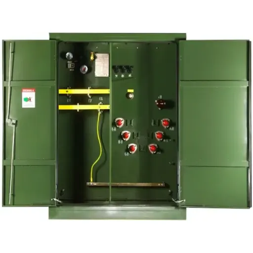
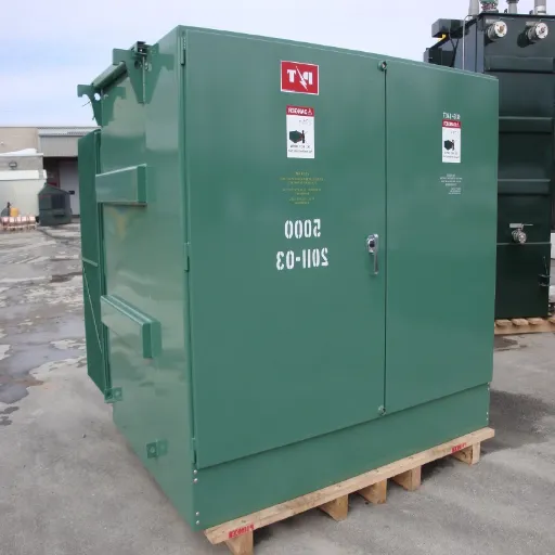
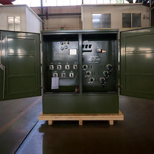
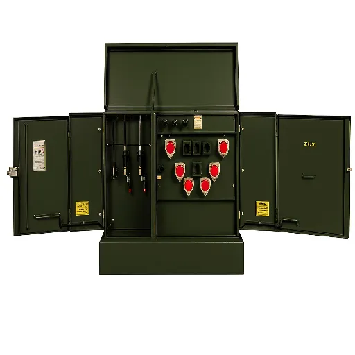
Several advantageous properties of the transformer are that it is completely enclosed and protected; it is also installed at the level. And since a pad-mounted transformer would exchange voltage on the last end in a very underground distribution network, they change a little medium-voltage primary power (typically 4.16kV to 34.5kV) for use at common utility voltages using 208Y/120V, 480Y/277V, or 4160V for the commercial, industrial, or utility customer.
Unlike pole-mounted transformers, which are hoisted up and out of reach by utility linemen when checking lines, pad-mounted units stand in enclosures with dead-front and lockable doors for installation at street-level. That’s because, usually, these types of transformers are the preferred solution for installing them at ground-level locations with restricted access from public points, in addition to situations which involve underground cabling or safety concerns.
Essential in every installation is the three-phase design for balanced power distribution across three phases. In an industrial setting, a three-phase pad-mounted transformer is essential because the system requires additional star or delta load balancing. For commercial building data centers, or even large-scale electric vehicle charging facilities and utility-scale renewable energy projects, balanced power between phases, motor compatibility, and high kVA capacity are required.
In typical distribution systems, the three-phase compact secondary substation or pad-mounted transformer sits at the end of the MV cable run, feeding a low-voltage switchboard or main distribution panel. The transformer is the interface between the utility’s distribution system and the customer’s facility power system. Specifications matter more than most engineers realize. Default settings can always be changed, but when things go wrong in the setup, it could mean a lot of opportunities lost.
Three-Phase Pad-Mounted Transformer Specifications
Standard kVA Ratings
Three-phase pad-mounted transformers are manufactured across a wide kVA range to match load requirements. Standard ratings recognized under IEEE C57.12.34 include:
| kVA Rating | Typical Application |
|---|---|
| 75 – 300 kVA | Small commercial buildings, retail, light industrial |
| 500 – 1,000 kVA | Medium industrial, multi-tenant commercial |
| 1,500 – 2,500 kVA | Large industrial facilities, data centers, and hospitals |
| 3,750 – 10,000 kVA | Utility substations, campuses, and large manufacturing |
Most procurement engineers select from the 500 kVA to 2,500 kVA range, where the three-phase pad-mounted transformer serves the broadest commercial and industrial applications.
Voltage Configurations
Typical primary voltage ratings range from 4160-V to 34 500-V in the most series wave network with the utility. Typical primary voltage systems cover 12 470-V and 13 200-V, primary voltages and 13 800-V and 34 500-V in North America, for distribution.
The assignment of secondary voltage depends on the loads:
- 208Y/120V: normal commercial building installation with 3-phase (four-wire)
- 480Y/277V: industry and commerce with 3-phase, this is often used for motor loads and lighting
- 240 delta / 480V delta: usual in industrial motor applications
- 4,160V: Will be used as a tapping point where voltage needs to be reduced to a medium level with massive motor loads.
These have multi-tap primary windings with standard designs that allow a variation of +2.5 percent on the primary side and +5 percent on the primary side, field adjustable to compensate for voltage variations on the primary distribution circuit.
Temperature Rise and Cooling Classes
Temperature rise limits in oil-immersed pad-mounted transformer insulator are defined according to IEEE Standard C57.12. 34. ONAN forced circulation (oil natural, air natural) is the standard cooling class of the three-phase pad-mounted units, meaning convection alone is employed in natural cooling of the transformer oil and air atmosphere of the transformer without introducing any forced fans or pumps.
So, the maximum allowable average winding temperature rise above ambient for ONAN units is around 65°C, with a maximum ambient temperature of 40°C, which implies that we’re allowed about a maximum winding hotspot temperature of 110°C.
Higher site ambients or long-duration overloads might entail that the unit rating is downgraded. To derive the derating factor required for desert-type ventilation systems or hermetically-sealed substations, you have only to ask the manufacturer according to the similar ambient conditions of the site concerned.
Impedance and Vector Groups
Apart from fault current calculations and transformer paralleling, the impedance voltage is a critical parameter of interest. The impedance voltage was defined under the ANSI/IEEE guidelines for the standard impedance of a three-phase pad-mounted transformer, given as:
- 75 – 500 kVA: 2.0% to 4.5% impedance
- 500 – 2,500 kVA: 4.5% to 6.0% impedance
- 2,500 KVA and larger: 5.5% to 7.5% impedance
Common vector groups are Dyn11 (primary delta, secondary star point with neutral, and 30-degree phase shift) and YNyn0 (star, star c both neutral connections). The Dyn11 arrangement is widely seen in the U. S. It gives a firm second-side neutral block and prevents zero-sequence power from feeding back into the primary network.
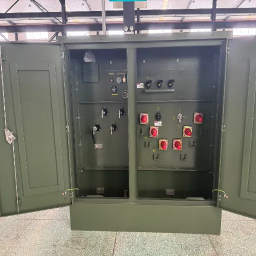
Types and Configurations
Loop Feed vs. Radial Feed Transformers
Three-phase pad-mounted transformers have two primary cable connection configurations: radial feed and loop feed, also called loop-through.
In radial feed, a single cable is provided on the primary side. One-way power flow is found where the feeder cable fails at the upstream, and the transformer dies. It is the simpler configuration with low costs and is appropriately used when utilities perform the bypass backup via a switch at a different locality.
While loop feed, two cables are connected on the primary side, which allows the distribution cable to run through the transformer cabinet and proceed to another transformer in the same circuit. Whenever a cable piece is damaged, electricians can work out the fault and get the power supply for the upcoming transformers on the loop from the next feed side. Loop feeding is required by most utilities for underground residential distribution, and that is why there is an increasing request for its application in commercial sectors where reliability is vouched for.
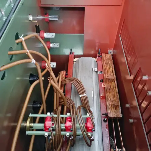
Internal load-break elbows and separable connectors from both primary cable sets are integrated into loop-feed units, which permit connection and disconnection of both live-front and dead-front under load.
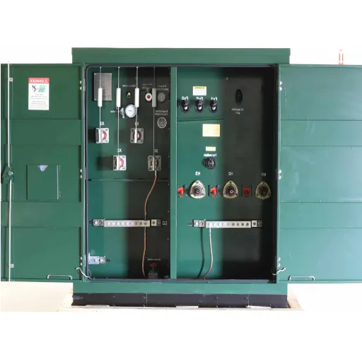
Dead Front vs. Live Front Bushings
The primary advantage of dead front design is the use of a fully enclosed energized conductor; in contrast, the live front’s uninsulated bushings are under the unit itself. In dead front design, all conductors, with one exception, have a deadface or test point, typically addressing underground or outdoor applications.
Preference is given to live front designs, which are designed for safety, convenience in maintenance, and may require greater clearances in the transformer’s design. The cables will have a dead metal front that is all but absent when they are connected. Affero a dead front class today is indeed the preference with all modern three-phase pad-mounted transformers for underground distribution using such a dead front primary connection as per ANSI/ICEA S-108-720.
This approach exposes the uninsulated bushings, located within the transformer compartment. They require greater clearances and are only suitable for qualified lineman access under strict energized conditions. As new today, they could hardly be seen in installations and are mostly found only in older systems or specific utility applications where the utility standard calls for them.
Industry Standards and Certifications
IEEE C57.12.34 Requirements
It is considered the standard in IEEE C57.12. 34 that all pad-mounted distribution transformers fit into the compartmental type, with a natural air cooling system for self-range voltage applications within 34,500V to 10,000kVA. List down the requirements listed below:
- Electrical and mechanical performance
- Voltage ratings and taps
- Impulse withstand levels (BIL)
- Audible sound levels
- References to nameplate data
- Liquid (oil) requirements
North American utilities require a device that conforms to the provisions listed in IEEE C57.12. 34. Almost all utilities demand such a sort of specification for supplying their customers with a three-phase padmount transformer in the US and Canada.
DOE Energy Efficiency Regulations
The code requires that the US Department of Energy be consulted on all this with regard to distribution transformers that are liquid-immersed-phase power units. Efficient-energy standards require that for all transformer units sold in the United States, there should be compliance with the United States-developed and mandatory efficiency levels, DOE 2016 TP1.
The required efficiency of a 1000 kVA, three-phase transformer, 13,800-to-480 V at 50% load is about 99.17%. It has a great impact on the selection of core steel and winding design, and this reflects an actual change in lifecycle operating cost savings.
An imported unit should always be scrutinized against the quotes to ensure it meets the DOE requirements of 10 CFR Part 431 efficiency, USA. Many units that are specifically tailored with the international market in mind are not manufactured following orders of the required U. S. Department of Energy’s efficiency levels.
NEC Article 450 and NFPA Standards
NEC 450 covers a transformer’s installation, with rules for protection, accessibility, ventilation, and marking requirements. For an outdoor pad-mounted transformer installation, the main requirements by the NEC include:
- The transformer would have to have monitored access to only qualified persons.
- Oil outdoor transformers must have containment if within 10 feet of the building.
- Conditions for overcurrent protection depend on impedance and primary current.
Arc flash hazard analysis and PPE specifically cover protocol for personnel working near energized transformers as well as in compliance with NFPA 70E. Conduct an arc flash study based on the fault current and clearing time at the time the installation becomes live.
Applications and Use Cases
Commercial and Industrial Facilities
Three-phase pad-mounted transformers are the standard solution for medium to large commercial buildings, manufacturing plants, hospitals, universities, and mixed-use developments served by underground distribution. They provide the interface between the utility’s underground feeder cable and the building’s main switchboard.
An investment for a 500,000 sq ft manufacturing facility must be in an appropriate, well-specified unit such as a 1,500-KVA, 13,800: 480Y/277-V (dead front) loop feed pad-mounted transformer with the 65°C rise, aluminum windings, meeting the DOE 2016 TP-1 efficiency standards. Before equipment order, installation of the concrete pad, enclosure grounding, and secondary cable connections of the equipment must be considered to comply with the utility’s distribution standards.
Renewable Energy: Solar and Wind Farm Applications
For the three-phase pad-mounted transformers, the highest growth application has been made in the renewable energy utility, including hundreds of these for utility-scale solar farms. Such solar facilities, which are spread over several acres with hexagonal forms, are made up of hundreds of thousands of solar panels/multicrystalline silicon.
The solar field is capable of generating 50 MW and is located in New Mexico. The commissioning is composed of 48 pieces of 1,000kVA three-phase transformers, exporter stepped up to 34.5 kV from the inverter output voltage of 480V for the collection point delivery of circuits. These units are fed loops with 150kV BIL to handle switching surges in typical solar collection circuits. Non-sinusoidal outputs are produced by the inverters. Imposed on any other note, the specification shall be tagged with the K-factor rating of K-4 to handle the ensemble harmonic heating involved.
For solar utility applications, confirm the K-factor rating, BIL level, and the harmonic content from the inverters before finalizing the transformer specifications.
Data Centers and Critical Infrastructure
In another implication, data centers are just as important when it comes to growth; a modern-day hyperscale data center at 50MW or more could very well deploy dozens of 3-phase pad-mounted transformers as secondary unit substations. These transformers are the stage where utility supplies are converted down from 13.8 or 34.5 kV to 480V UPS structures and power distribution units.
Data center applications often necessitate double-capacity transformers with N+1 or sometimes 2N configurations, such as runtime transformers. These transformers must be situated to ensure switching in just milliseconds, from one utility grid, within normal network circumstances, to on-site generation. Acoustic noise levels will be handled in most typical suburban or mixed-use sites; therefore, make sure the mention meets NEMA TR-1 sound level requirements concerning the installation environment.
EV Charging Infrastructure
An enormous wilful deployment of electric vehicles (EVs) requires 500 kVA to 2,500 kVA of 3-phase pad-mounted transformers for installing highway fast-charging hubs and fleet depots. The single 20-port DC fast recharge station, with 150-kW lungs, rates up to 3,000 kW of connected charge capacity, which translates into three 3,750 kVA transformers or two 2,000 kVA transformers in a parallel setup required for such enormous deployments of energy/operational systems.
Electric-Vehicle (EV) charging loads pose a difficulty due to quick, erratic load cycles with big harmonic content from the charging rectifier. Transformers should have high K-factor ratings (K-9 or higher) for EV charging applications.
Ready to specify the right transformer for your project? Contact our engineering team for a custom quote based on your load profile and site conditions.
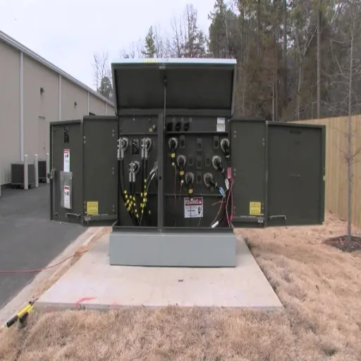
Installation Requirements
Site Preparation and Concrete Pad Specifications
A properly made concrete foundation is an obligation and therefore serves as the mechanical foundation of the installation, followed by meeting IEEE C57.12. 34-dimensional requirements for the specific transformer pad size. Baseplate design requirements are very difficult to meet and must be:
- level to within 1/8 in per foot
- Reinforced concrete with a minimum capacity of no less than 3,000 psi.
- Designed to support the transformer weight, including oil, plus a 25% safety margin
- Greater than the base of the transformer by at least 6 inches beyond that tangent in all directions
- Anchored by suitably anchored bolts in accordance with the manufacturer’s installation drawing
During construction, burial of secondary cable conduit bends disposed in the pad slab while being cast is a better way to form conduit placements because coring into a placed pad is significantly harder to learn. Finalize pulling tensions, conduit size, and cable routing with the utility engineering team before making the primary cable to the electrical vault entry from the utility vault.
NEC Clearance Requirements
The smallest clearances to be maintained around pad-mounted transformers have been established according to Article 450 from the NEC and IEEE C57.12. 34. The minimum norms are:
- Front clearance (cable compartment door) of the transformer: 3.5 feet (minimum) and 10 feet (preferable) for the utility aisles
- Rear and sides: 3 feet (minimum)
- Above: None required, but always make sure to have a lifting opening and provision for oil sampling
- Distance from buildings: Regulated by IEEE and building fire codes; however, oil-insulated transformers located 10.00 feet from combustible buildings will require secondary containment
Most utilities and AHJs (Authorities Having Jurisdiction) require a greater distance. Kindly consult the local utilities engineering department before finalizing the equipment pad site on the site plan.
Sizing and Selection Guide
kVA Calculation Formula
The fundamental sizing formula for a three-phase pad-mounted transformer is:
kVA = (Voltage x Amperes x 1.732) / 1,000
Where:
- Voltage = secondary line-to-line voltage
- Amperes = full load secondary current (sum of all connected loads)
- 1.732 = square root of 3 (three-phase constant)
For example, a facility with a connected load of 2,400 amperes at 480V three-phase requires:
kVA = (480 x 2,400 x 1.732) / 1,000 = 1,996 kVA
Select the next standard size up: a 2,000 kVA unit.
Load Factor and Future Expansion Planning
Transformers should never be sized to operate at 100% of nameplate ratings for the load. IEEE and ANSI loading guides suggest that continuous loadings should be allowed to remain at about 80-85% of nameplate KVA to have good thermal margins and at the same time, increase equipment life. On 80% loading for example, a 2000kVA transformer accounts for a connection to a connected load point of 1600 kVA continuously.
Consider diversity in developing peak demand. As a rule, not all the individual loads will be turned on in most commercial and industrial buildings at the same time. It may be that the true value of the coincident peak demand is between 60% and 80% of the sum of individual load nameplate ratings.
Growth is planned. If your facility wants to expand production capacity, install EV charging, or extend the data center within the life of the transformer (usually 20-30 years), then make the maximum demand projections, instead of only loading near current levels. Transformer upgrades are costly and inevitable. Being clever about the kVA rating at the initial installation is always cheaper than having to redo it five years after installation.
Maintenance Best Practices
Reactive maintenance is not usually necessary for a three-phase pad-mounted transformer, relative to other electrical equipment, but when regular inspections are neglected, it steers the course for rapid deterioration and the possible occurrence of catastrophic damage due to sudden failure.
The annual visual inspection includes:
- Inspect the outer enclosure for signs of corrosion, physical damage, or forced entry.
- Monitor all gaskets and seals for oil leakage (even the smallest leakage level indicates seal deterioration)
- Check the oil level inside the glass.
- Inspect the bushing and the cable terminations for evidence of tracking, cracks, or corona damage.
- Check that ground conductors remain connected and properly grounded.
Every three to five years:
- Obtain oil samples for dissolved gas analysis (DGA) to identify hydrogen, methane, acetylene, and other gases indicating internal faults before they cause and lead to failure.
- Test dielectric breakdown voltage (BDV) to assess the quality of oil insulation.
- Scan hot spots from a distance when making use of the infrared camera in order to load an object.
In case the results of the DGA indicate an increased acetylene or CO2, then immediately an in-depth diagnosis must be performed by a professional. Acetylene is an indication of an active internal fault in making transformer oil due to arcing.
Cost Considerations and 2026 Market Trends
2026 Price Ranges by kVA Rating
The transformer market remains tight in 2026. Prices have stabilized from the 2022-2024 peak but remain 60-80% above pre-pandemic levels for most standard units.
| kVA Rating | Estimated Price Range (USD) |
|---|---|
| 75 – 150 kVA | 5,000–5,000–9,000 |
| 500 kVA | 14,000–14,000–28,000 |
| 1,000 kVA | 42,000–42,000–60,000 |
| 2,500 kVA | 125,000–125,000–190,000 |
Lead times from domestic manufacturers range from 40 to 65 weeks for standard configurations. Custom specifications or non-standard voltages can push lead times to 80+ weeks. For projects with hard commissioning deadlines, placing equipment orders at or before preliminary design approval is now standard practice.
Total Cost of Ownership
More than the price of tapes is the total cost of ownership. These are the components that, over a 25-year service life affect total cost ownership (TCO) for the three-phase pad-mounted transformer system:
- No-load (core) losses: present 24 hours a day, every day, regardless of whether the load is heavy.
- Load losses: present only when current flows; increase with load squared
- Maintenance costs: with oil testing, inspections, and potential repairs
- Probability in terms of replacement costs and downtime: if the unit fails prematurely
A higher-efficiency unit may cost a premium at purchase, carrying fewer core losses, such as an add-on of $3,000 to $8,000, with operational savings of $15,000 to $40,000 over the service life at current prices for electricity saved. Define levels of loss in procurement documents rather than simply as a “manufacturer’s standard.”
Choosing a Three-Phase Pad-Mounted Transformer Manufacturer

The quality of equipment, along with the accessibility to technical support, warranty service, and spare parts over a service life of 25-30 years, largely depends on the manufacturer you choose.
Checklist for Key Evaluation
- Compliance with IEEE C57.12. 34: demand performance certificates as well as type tests
- DOE efficiency certifications: Look up Provisions of 10 CFR Part 431, as applicable to installations in the U. S.
- Quality certifications: ISO 9001 certifications are an assurance that documented quality management has been maintained in the organization.
- Factory acceptance tests: Typical factory tests are ratio, polarity, resistance, insulation resistance, and applied potential; they require test reports from each unit.
- Lead times and delivery performance: Request documentary examples of on-time delivery performance from existing customers.
- After-sales service: Check whether application engineers, spare parts, and warranty services are available in your region.
- Customization of capabilities: The assertion of such occasion is the manufacturer’s ability to fabricate non-standard voltages, K-factor ratings, or specialized enclosures, but not at a premium or without additional lead time.
Shandong Corporation Electric Company Ltd. manufactures, among others, three-phase pad-mounted transformers within the kVA rating range of 75-10,000 in compliance with IEEE C57.12. 34, IEC 60076, as well as DOE 10 CFR Part 431. The team of engineers with which the engineering operates also provides the final specifications and value-engineered input to the project engineer. Load calculations undergo review, and each finished product is shipped in accordance with the project’s technical requirements.
Request a custom specification and quote from our engineering team.
Frequently Asked Questions
What is the difference between a pad-mounted transformer and a substation transformer?
Pad-mounted transformers are such electrical transformers that operate at ground level and become solid and better functioning as transformers. Such transformers primarily take into consideration how a business more often powers itself alone, or a small number of customers if voltage falls at 34.5 kV, up to 10 MVA. Substation transformers also combine with large and high-voltage transmission class units, mostly over 69 kV, which is used for serving the vast distribution areas. They would still use separate switchgear and are not self-contained.
What does dead front mean on a three-phase pad-mounted transformer?
Dead front is a term and a stage of the terminal cable type. Instead of the exposed energized conductors on the cable termination of the transformer, the dead front model uses fully-insulated and submersible elbow connectors. This significantly increases the safety of access for utility personnel doing work on underground systems.
How do I select between loop feed and radial feed configurations?
Loop feed configurations are much better when it comes to reliability, as they allow power to be channelled from two directions in the primary feeder. Most often, loop feed is a requirement in their standards for underground distribution in residential-commercial applications. Radial feed is easier, cheaper and ensures reliability without any route to feed when the cable upstream fails. Ascertain the standard distribution utilities in your territory before any specific conditioning.
What kVA size is typical for a commercial building?
A 5,000 and 10,000-sq. A ft. residential building of flats may require from 75 to 150kVA. An office building of 100,000 sq. ft. should need from 500 to 1,000kVA. The large hospital or the universities may require such capacity as 2,500 kVA and above. Calculate the specification from the connected load calculated by applying the diversity factor to it, not based on the judgment of thumb alone.
What type of transformer oil is standard for pad-mounted transformers?
ASTM D3487 Type II has listed naphthenic mineral oil as an insulated property due to its medium-transformer oil. Some suppliers are having ester fluids (natural or synthetic) for higher fire safety (higher flash point) and biodegradability. Such fluids are specified in cases where mineral-based oil is restricted by local building codes or near bodies of water up to sensitive environmental areas.
How long does a three-phase pad-mounted transformer last?
Such a unit, loaded correctly and maintained properly, will last up to 25 to 30 years and even longer. But chronic overloading (more than 100% of nameplate continuously) or deferred maintenance has a negative influence on life expectancy. For units running up to 80% or below of their nameplate capacity, the life expectancy is frequently 35 to 40 years.
What are the clearance requirements around a pad-mounted transformer?
According to NEC Article 450, there is a requirement for at least 3.5 feet of clear work space to be kept in front of the transformer cabinet door. Larger clearances are required by many utilities and local jurisdictions for emergency vehicle access to be 10 feet in front. Verify this with your utility’s engineering department before final site location selection for the pad.
Conclusion
The three-phase pad-mounted transformer is the most significant high-technology equipment located in the very center of its underground distribution system. Getting the specification right before you place the order determines whether the unit will perform flawlessly for the subsequent thirty years or be problematic from the very first operational step.
Essentially, prime specification parameters to confirm before ordering are:
- The load calculation is rated at 80 percent above peak demand with growth
- Matching primary and secondary voltage levels to the utility feed and facility requirements
- Primary feed and secondary loop radial, per utility drawings
- I EEE C57.12. 34 compliance with energy efficiency DOE certification, CFR Part 431, 10
- BIL, corresponding to the primary voltage class
- K-factor rating if the load has significant harmonic content associated with it
- No-load and load loss are set forth explicitly by procurement documents
One of the riskiest steps that an engineer or a project manager can undertake in risk management today is ordering pieces of equipment as early as possible in the project schedule. A 40- to 65-week lead time might cause a transformer that is ordered at final design approval to actually be delivered after the original commissioning date.
Leaf from downstream of Shandong Electric Co., Ltd. is the maker of three-phase pad-mounted transformers in the complete range of standard kVA rating, with its back engineered to support an envisaged tailored configuration, abnormal voltage, or project-specific induction. At capacity to IEEE C57.12. 34, IEC 60076, and DOE 10 CFR Part 431 standards, our manufacturing sites run in line with ISO 9001 certification for quality management and with factory acceptance tests on every unit.
Contact our engineering team to discuss your project requirements and receive a technical specification review and competitive quote.