
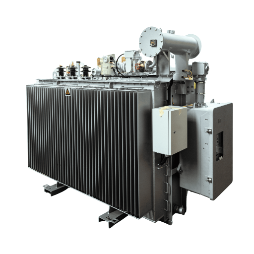
Hospital Transformer: Selection, Standards, and Installation Guide

Hospitals require medical-grade isolation transformers for their patient-critical circuits while they need dry-type transformers to distribute power throughout their facilities and K-rated transformers to handle non-linear medical imaging loads. The selection process needs to follow IEC 61558-2-15 and NFPA 99 and all applicable local healthcare electrical regulations.
A hospital experience transformer failure when it leads to equipment downtime which results in lost surgical procedures and ventilator system breakdowns and potential regulatory breaches that endanger hospital certification status. Hospital electrical systems face downtime which results in financial losses between 8000 to 15000 dollars for each minute they remain nonoperational. Hospital engineering teams and healthcare EPCs approach transformer specification through commercial building standards which leads to their failure to recognize the specific requirements that differentiate healthcare power systems.
This guide covers exactly how to specify, size, and procure transformers for hospital and healthcare facilities. You will learn the differences between medical isolation and standard dry type construction, how to calculate kVA for hospital-specific loads, why K-13 ratings are mandatory for imaging departments, and what standards apply from patient wards to operating theaters.
Key Takeaways
- Patient-area circuits require medical isolation transformers per IEC 61558-2-15 with leakage current below 0.5 mA and test voltage of 4 kV.
- General hospital power uses dry type transformers (cast resin or VPI) due to indoor fire safety and low maintenance requirements.
- MRI, CT, and surgical equipment generate significant harmonics, making K-13 rated transformers essential for imaging department electrical rooms.
- Hospital transformer noise must stay below 45 dB in patient care areas and below 55 dB in general electrical rooms per HTM 06-01 guidelines.
- A practical procurement checklist covers 12 items from isolation rating and leakage current to thermal monitoring and factory witness testing.
Why Hospitals Require Specialized Transformers
Patient Safety and Electrical Isolation
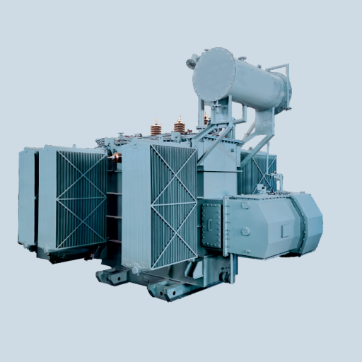
Patient safety is the defining priority for hospital electrical design. In standard commercial buildings, a ground fault might trip a breaker. In a hospital patient care area, the same fault could deliver dangerous current through a patient connected to monitoring equipment or an infusion pump. Medical isolation transformers are engineered to limit leakage current and provide galvanic separation between the primary supply and the secondary circuit serving patient areas.
IEC 61558-2-15 specifies that medical isolation transformers must limit leakage current to 0.5 mA maximum under normal conditions and withstand a test voltage of 4 kV between primary and secondary windings. Standard distribution transformers are not designed to these tolerances. Using a conventional transformer in a patient environment risks exceeding safe touch current limits and failing regulatory inspection.
Fire Safety in Healthcare Environments
Hospitals operate around the clock with occupied beds, surgical suites, and intensive care units that cannot be evacuated quickly. Fire safety codes for healthcare facilities are therefore among the strictest of any building type. Oil immersed transformers are almost never installed indoors in modern hospitals because the fire risk and oil containment requirements conflict with NFPA 99 and local building codes.
Dry type transformers eliminate the liquid fire hazard entirely. Cast resin transformers use vacuum-cast epoxy that is self-extinguishing and produces no toxic smoke. VPI dry type transformers use polyester resin impregnation that provides excellent moisture resistance and thermal performance. Both types satisfy the fire safety priorities that make dry type transformers the standard for hospital indoor installations.
Power Quality for Life-Critical Equipment
Hospital electrical loads are a mix of life-critical and highly sensitive equipment. Ventilators, infusion pumps, patient monitors, and anesthesia machines require stable voltage with minimal fluctuation. Medical imaging equipment — MRI, CT scanners, angiography systems — draws non-linear current with total harmonic distortion of 20 to 35%. These harmonics can cause voltage distortion, overheating, and premature failure in transformers not rated for non-linear duty.
Power quality in hospitals is not a convenience. Voltage sags from inadequate transformer capacity can cause CT scanners to abort scans, wasting contrast media and rescheduling patients. Harmonic distortion from undersized neutrals can create intermittent faults in sensitive monitoring equipment. The transformer is the first line of defense for power quality throughout the facility.
Noise Sensitivity in Patient Care Areas
Transformer noise is often underestimated in hospital design. Patient wards, recovery rooms, and neonatal units require quiet environments for healing and rest. The HTM 06-01 guideline recommends maximum 45 dB transformer noise in ward areas and 55 dB in general plant rooms. Standard NEMA ST-20 designs may exceed these limits, especially as transformer capacity increases.
When Dr. Elena Vasquez, chief of engineering at a 400-bed urban hospital in Sao Paulo, reviewed the electrical installation during a wing expansion, she discovered that the contractor had installed standard distribution transformers in a substation with shared ductwork to patient rooms above. The units generated 58 dB — well above the 45 dB limit for ward areas. Patient complaints about humming noise started within the first month. The retrofit to low-noise isolation transformers, plus acoustic lagging on ductwork, cost $38,000 and delayed the wing opening by two weeks. A noise specification written into the original procurement would have prevented the problem entirely.
Want to understand how transformer construction affects noise output? Review our dry type transformer guide for a detailed breakdown of core design and sound reduction options.
Types of Transformers Used in Hospitals
Medical Isolation Transformers (IEC 61558-2-15)
Medical isolation transformers are purpose-built for patient environments. They provide galvanic isolation between the incoming supply and the medical circuit, limiting leakage current to safe levels even under single-fault conditions. Key design features include reinforced insulation, electrostatic shields between windings, and thermal protection that meets medical-grade standards.
These transformers are required in Group 2 medical locations per IEC 60364-7-710, which includes operating theaters, intensive care units, cardiac catheterization labs, and dialysis treatment areas. They are not optional upgrades. They are mandatory for compliance.
The primary specification difference from standard transformers is the leakage current limit. While a conventional transformer might allow 3 to 5 mA of leakage current, a medical isolation transformer must stay below 0.5 mA. This requires specialized winding techniques, higher-grade insulation materials, and 100% production testing.
Dry Type Transformers for General Power
For non-patient areas — administrative offices, kitchens, laundry, parking structures — standard dry type transformers provide reliable voltage transformation without the medical-grade isolation premium. Cast resin and VPI constructions are both suitable, with cast resin preferred in high-humidity climates or where maximum fire safety is desired.
General power transformers in hospitals still benefit from low-noise design. Even administrative areas in modern hospitals are often located adjacent to clinical zones, and noise transmission through building structure can affect patient comfort. Specifying noise levels 5 to 10 dB below standard NEMA limits is a low-cost insurance policy.
K-Rated Transformers for Imaging and Surgery
Medical imaging equipment represents one of the most challenging electrical loads in any building. MRI scanners use switched-mode power supplies that draw pulsed current. CT scanners create high inrush during gantry rotation. Angiography and fluoroscopy systems generate continuous harmonic content. Together, these loads can produce total harmonic current distortion of 20 to 35%.
Standard K-0 transformers are not designed for this duty. The harmonic currents create additional eddy current and stray losses in the windings and core, raising operating temperature beyond insulation limits. K-rated transformers address this with oversized neutral conductors, lower flux density, and reinforced winding designs.
For hospital imaging departments, K-13 is the minimum safe specification. Facilities with multiple MRI or CT units, or hybrid operating rooms with integrated imaging, should consider K-20 to provide additional thermal margin.
Emergency Power Transformers (Generator Backup)
NFPA 99 requires essential electrical systems in hospitals to have two independent power sources: normal utility supply and emergency standby power. The emergency system typically uses diesel generators with automatic transfer switches. Transformers in the emergency power path must be sized to carry life safety and critical branch loads simultaneously.
Emergency transformers should be separate from normal power transformers, not just switched. This separation prevents a fault in the normal system from affecting emergency capacity and simplifies maintenance without shutting down life support systems.
Hospital Transformer Standards and Compliance
IEC 61558-2-15 — Medical Isolation Transformers
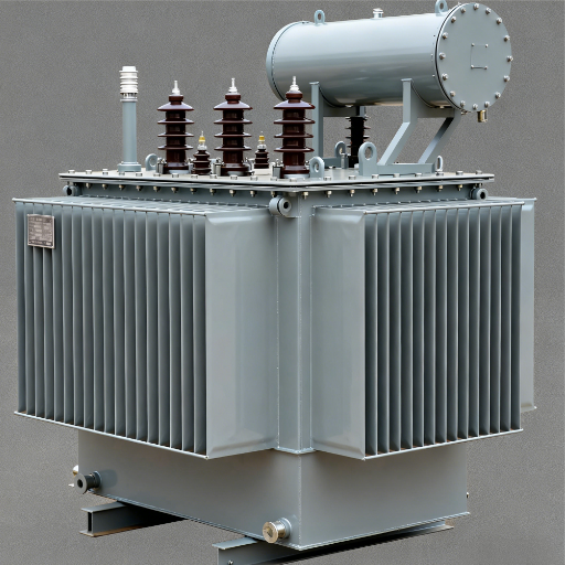
IEC 61558-2-15 is the definitive standard for medical isolation transformers. It defines construction requirements, test methods, and performance limits specifically for transformers used in medical locations. Key requirements include:
- Maximum leakage current of 0.5 mA under normal conditions
- Dielectric strength test of 4 kV between primary and secondary
- Thermal class and overload protection requirements
- Marking and documentation standards
Transformers claiming medical-grade isolation must be tested and certified to this standard. A standard IEC 60076 transformer with isolation does not automatically meet IEC 61558-2-15. Always request the compliance certificate and test report.
NFPA 99 — Healthcare Facilities Code
NFPA 99 governs the complete electrical infrastructure of healthcare facilities in the United States. It defines the essential electrical system, branch classifications (life safety, critical, equipment), and requirements for power sources, distribution, and grounding. Transformer selection must align with the facility’s electrical system category as defined by NFPA 99.
Category 1 facilities (hospitals with inhalation anesthesia) have the most stringent requirements. Category 2 facilities (outpatient surgical centers, clinics) have reduced but still significant requirements. The transformer specification must match the category, not exceed it unnecessarily or fall short of critical requirements.
HTM 06-01 and Local Healthcare Electrical Codes
The United Kingdom uses HTM 06-01 to provide electrical service guidelines for healthcare facilities. The document establishes requirements for selecting transformers and determining noise limits and designing electrical rooms and separating normal from emergency systems. Many Commonwealth countries and former British colonies reference HTM 06-01 directly or have adapted similar standards.
Local amendments can impose additional requirements for seismic bracing, emergency egress, or spill containment. Always verify local healthcare electrical codes before finalizing transformer specifications.
EMC and Harmonic Compliance for Medical Equipment
Medical equipment must comply with electromagnetic compatibility (EMC) standards to prevent interference between devices. Transformers feeding medical equipment rooms should include electrostatic shields to attenuate conducted noise and transients. Shielded isolation transformers provide both patient safety and EMC protection in a single unit.
Harmonic compliance is equally important. IEC 61000-3-6 and IEEE 519 set limits for harmonic injection into the grid. While these standards primarily address the utility interface, hospital internal distribution must also manage harmonics to prevent voltage distortion that affects sensitive equipment.
How to Size a Hospital Transformer
Calculating Hospital Load Categories
Hospital load is not homogeneous. It falls into distinct categories with different duty cycles, power factors, and growth patterns:
- HVAC: 45 to 55% of total hospital electrical load. Chillers, air handling units, pumps, and fans operate continuously with seasonal variation.
- Medical imaging: 15 to 25% of total load. MRI, CT, X-ray, and angiography equipment have high momentary demand and significant harmonic content.
- General power: 10 to 15% of total load. Lighting, offices, kitchens, laundry, and general building services.
- Life safety and critical: 10 to 15% of total load. Emergency lighting, fire alarms, surgical equipment, and patient monitoring on backed-up circuits.
A common mistake is sizing the transformer for average load rather than peak simultaneous demand. In a hospital, imaging equipment, HVAC, and surgery schedules can align to create demand spikes that exceed average load by 30 to 50%.
Normal Power vs. Emergency Power Sizing
NFPA 99 requires separate sizing analysis for normal and emergency power systems. The emergency transformer must carry all life safety and critical branch loads if the normal utility fails. This includes operating room equipment, intensive care monitors, emergency lighting, and fire safety systems.
Emergency load is typically 40 to 60% of normal peak load, but it must be calculated explicitly. Never assume emergency capacity equals normal capacity, and never size emergency transformers smaller without a formal load analysis.
Worked Sizing Example — 300-Bed General Hospital
Consider a 300-bed general hospital with normal and emergency power requirements.
Step 1: Calculate normal power load categories
- HVAC: 1,500 kW
- Medical imaging: 800 kW
- General power: 400 kW
- Life safety/critical (normal mode): 300 kW
- Total normal load: 3,000 kW
Step 2: Convert to kVA at 0.90 power factor
- 3,000 kW / 0.90 = 3,333 kVA
Step 3: Apply 25% future growth margin
- 3,333 kVA x 1.25 = 4,166 kVA
Step 4: Select standard transformer rating
- Specify 4,000 kVA normal power transformer
Step 5: Calculate emergency power load
- Life safety/critical (emergency mode): 300 kW
- Essential HVAC (smoke control, OR ventilation): 600 kW
- Emergency lighting and alarms: 200 kW
- Total emergency load: 1,100 kW
Step 6: Convert emergency load to kVA at 0.90 power factor
- 1,100 kW / 0.90 = 1,222 kVA
Step 7: Apply 25% future growth margin
- 1,222 kVA x 1.25 = 1,528 kVA
Step 8: Select emergency transformer rating
- Specify 1,600 kVA emergency power transformer
This sizing ensures the hospital can grow into the design capacity without transformer replacement.
Future Growth and Redundancy Considerations
Hospital load grows faster than most building types. New imaging technology, expanded surgical capacity, and additional specialty units can increase electrical demand by 20 to 30% within five years of initial construction. Building a 25% growth margin into the initial transformer specification is standard practice. Building 40% margin is not excessive for teaching hospitals or facilities with active expansion plans.
When James Oduya, facilities manager at a rural 80-bed hospital in Kenya, sized the main transformer for nameplate HVAC load only, he believed he was being conservative. The 1,000 kVA unit handled the existing load comfortably. Two years later, a donor-funded CT scanner arrived. During the first peak cooling season with the new scanner running, the transformer overloaded on hot afternoons. The neutral conductor overheated from harmonic current. The upgrade to a 1,500 kVA K-13 unit cost $67,000 and required a three-day partial shutdown that cancelled outpatient clinics. The lesson is straightforward: always size for known future imaging expansion, not just today’s load.
Noise, Vibration, and Installation Requirements
Noise Limits for Hospital Transformers
Hospital noise standards are stricter than commercial buildings. HTM 06-01 recommends:
- Operating theaters and intensive care: 40 dB maximum
- Patient wards and recovery rooms: 45 dB maximum
- General corridors and administration: 50 dB maximum
- Plant rooms and electrical rooms: 55 dB maximum
Standard NEMA ST-20 noise levels range from 48 dB at 150 kVA to 67 dB at 2,500 kVA. A standard 1,000 kVA dry type transformer produces approximately 58 dB. In most hospital electrical rooms, this exceeds the adjacent patient area limit unless the room is well-separated and acoustically treated.
Low-noise design options include reduced flux density, step-lap core construction, and amorphous metal cores. These upgrades add 10 to 20% to transformer cost but prevent far more expensive acoustic remediation after installation.
Vibration Isolation Near Patient Areas
Transformer cores vibrate at twice the supply frequency (100 Hz or 120 Hz). This vibration transmits through mounting structures, building framing, and ductwork into occupied spaces. In hospitals with electrical rooms adjacent to or below patient areas, vibration isolation is essential.
Spring isolators or high-deflection rubber pads should be specified between the transformer base and the housekeeping pad. The isolator deflection must match the transformer weight and operating frequency. Building structure-borne noise paths should be reviewed by an acoustic consultant for critical locations.
Electrical Room Ventilation and Clearance
Dry type transformers require adequate ventilation to maintain rated temperature. For every 1 degree C above rated ambient, insulation life decreases by approximately 0.5%. Hospital electrical rooms should maintain ambient temperature below 40 degrees C under maximum load conditions.
NFPA 70 establishes required clearances which need to be maintained to ensure safe operations together with maintenance access points. The equipment needs space at its front for terminations and at its sides for cooling airflow and at its rear for inspection purposes which needs to be established before the equipment arrival. The electrical rooms in hospitals need constant operation so all access points must provide sufficient space to avoid future operational interruptions.
Separation of Normal and Emergency Transformer Rooms
Best practice separates normal and emergency transformers into different rooms or at minimum different fire-rated compartments. This separation prevents a fire or fault in one system from affecting the other and allows maintenance on normal power equipment without de-energizing emergency circuits.
When separation is not possible due to building constraints, fire-rated barriers and independent ventilation systems should be specified. The emergency transformer room should have direct exterior access for generator connection and maintenance without entering the main hospital building.
UPS and Backup Power Integration
Transformer Placement in UPS Architecture
Hospital UPS systems protect critical loads during the interval between utility failure and generator startup. Typical diesel generators require 10 to 15 seconds to reach rated speed and accept load. During this interval, the UPS battery sustains critical equipment.
Transformer placement relative to the UPS affects both harmonic management and fault coordination. An input isolation transformer upstream of the UPS protects the upstream distribution from UPS rectifier harmonics and provides voltage transformation from medium voltage to UPS input voltage. A step-down transformer is commonly used for this function.
Output transformers downstream of the UPS provide voltage matching to panelboard input requirements. In either position, the transformer must be K-rated if the UPS generates significant harmonic content.
K-Factor Requirements for UPS Harmonics
Double-conversion UPS systems draw current in pulses, generating total harmonic current distortion of 15 to 30% at the input. The 3rd harmonic and its odd multiples add in the neutral conductor. A standard K-0 transformer specified for a hospital UPS system will overheat.
K-13 is the minimum safe K-factor for hospital UPS applications. Facilities with large UPS systems protecting multiple operating theaters or the entire critical branch should consider K-20. The additional cost is minimal compared to the cost of emergency replacement during a patient care emergency.
When a specialty surgical center in Bangkok installed a new 200 kVA UPS system for their three operating theaters, the electrical contractor used standard K-0 transformers downstream to save on initial cost. During a grid outage in the monsoon season, the UPS switched to battery and the transformers overheated from harmonic current within 18 minutes. Theater two was in the middle of a orthopedic procedure. The surgical team completed the case under emergency lighting while the backup generator was manually started, but the incident triggered a regulatory review and temporary suspension of elective surgery. The K-13 retrofit, planned correctly from the start, would have cost 12,000insteadof12,000insteadof31,000 with emergency labor and regulatory remediation.
Ready to validate your hospital’s transformer sizing and compliance requirements? Send your facility specifications to our engineering team for a detailed review.
Generator Synchronization and Transformer Sizing
Emergency generators must synchronize with the hospital load before transfer. The transformer feeding the emergency distribution panel must handle the inrush current when the generator closes onto the load. Generator manufacturers provide maximum allowable voltage dip during transfer, and the transformer impedance must be selected to keep voltage dip within acceptable limits for life support equipment.
Transformer impedance of 4 to 6% is typical for hospital applications. Lower impedance reduces voltage drop but increases fault current. The impedance selection should be coordinated with the generator manufacturer, switchgear supplier, and protection engineer as part of the overall system design.
Procurement Checklist for Hospital Transformers
Use this checklist when requesting quotations or evaluating supplier proposals for hospital projects:
- kVA Rating: Confirm total load plus 25% growth margin, with separate analysis for normal and emergency power
- Isolation Rating: Medical-grade isolation per IEC 61558-2-15 for patient areas; standard isolation acceptable for general power
- Leakage Current Limit: 0.5 mA maximum for medical isolation transformers serving Group 2 locations
- K-Factor Rating: K-13 minimum for imaging departments and UPS-fed circuits; K-20 for high-harmonic environments
- Noise Level: Maximum dB at 1 meter, referenced to HTM 06-01 limits for adjacent room types
- Insulation Class: Cast resin or VPI; fire rating suitable for NFPA 99 requirements
- Standards Compliance: IEC 61558-2-15, NFPA 99, IEC 60364-7-710, local healthcare electrical codes
- Efficiency: Full-load and 50% load efficiency; transformer efficiency at partial load matters for hospitals running below peak capacity
- Temperature Monitoring: RTD or thermistor provision for winding hot spot monitoring
- Factory Testing: Routine tests per IEC 60076-1 or IEEE C57.12.01; witness testing for medical-grade units recommended
- Delivery Schedule: Aligned with construction timeline; hospital projects rarely tolerate equipment delays
- Warranty and Technical Support: Extended warranty options; engineering support for installation and commissioning
A thorough checklist forces suppliers to confirm each requirement in writing. In healthcare procurement, verbal assurances are not enough. The compliance documentation must support accreditation inspections and insurance reviews.
Conclusion
A hospital transformer is a patient safety device, not just an electrical component. The wrong isolation rating risks leakage current in patient environments. The wrong K-factor leads to overheating in imaging departments. The wrong noise specification disrupts patient recovery. The wrong emergency power configuration threatens life support continuity.
The correct approach combines rigorous load analysis, standards-aligned specification, and honest attention to the healthcare environment. Start with the total facility load including HVAC, imaging, surgery, and life safety demand. Apply an appropriate growth margin for future expansion. Specify medical isolation transformers for all patient-critical circuits per IEC 61558-2-15. Select K-13 or K-20 ratings for imaging and UPS-fed loads. Match noise levels to the adjacent room type. Verify that emergency transformers are separate, adequately sized, and coordinated with generator synchronization requirements. And use the procurement checklist to ensure every supplier proposal addresses every requirement.
If you are planning a new hospital, expanding an existing facility, or upgrading transformers for new imaging equipment, send your specifications to our engineering team. We will review your load profile, compliance requirements, and environmental constraints, then recommend the most practical hospital transformer configuration for long-term reliability and patient safety.