Distribution Transformer: Complete Engineering Guide for Utility and Industrial Applications
The distribution transformer is a step-down transformer that changes the medium voltages such as 11 kV, 22 kV, or 33 kV coming from the utility grid to lower voltages usable by end consumers, usually 400 V three-phase or 230 V single-phase. This is the final transformation stage before the electricity reaches factories, commercial buildings, and residential areas, making a very important and under-recognized component in any power infrastructure project.
Most distribution transformer failures are attributed to not incorrectness in the manufacturing but the incorrect specification. An undersized unit for future load growth will not wear out immediately but will have a significantly shorter service life, due to overheating. On the other side, an overt-allotted unit would lose energy in no-load losses wherever it is supposed to operate. Particularly wrong selection of cooling will result in higher maintenance and would generally overshadow any slight cost advantages in procurement. This guide is intended to be very practically goal-oriented in giving specifications, together with installation and maintenance, ensuring the stated transformer delivers reliable service life over a span of 25-40 years.
Key Takeaways
- Distribution transformers are optimized for all-day efficiency at 50–75% load, not maximum efficiency at full load like power transformers.
- The four main types are pole mounted, pad mounted, oil immersed, and dry type; each suits a distinct installation environment and application.
- Correct kVA selection requires calculating connected load, applying a diversity factor, and adding 20–30% margin for future growth.
- Oil immersed units dominate outdoor utility applications, while dry type transformers are preferred indoors for safety-critical environments.
- Lifecycle cost — purchase price plus 20–30 years of energy losses — is a more important metric than upfront price alone.
What Is a Distribution Transformer and How Does It Work?
A distribution transformer operates on the other side of electromagnetic induction. The primary winding must produce alternator current, which builds a changing magnetic flux within the laminated steel core. Here, by inducement, the magnetic flux then causes a voltage to appear within the secondary winding. Due to the fact that the secondary winding has less turns than the first one, the voltage is then reduced at the same time that the current increases proportionally, resulting in a consistent power that respects the rule of conservation minus the losses mentioned before.
The key performance characteristic that separates a distribution transformer from a power transformer is its load profile. Power transformers at generation stations or transmission substations operate near full load for extended periods. They are designed for maximum efficiency at or near 100% load. A distribution transformer, by contrast, serves variable loads. A residential unit may run at 30% capacity at noon and 80% in the evening. An industrial unit may see sharp spikes during production shifts. Because of this, distribution transformers are optimized for all-day efficiency — the highest efficiency over a typical 24-hour load cycle — which usually occurs at 50–75% of rated capacity.
Voltage ratios vary by region and application. Common primary voltages include 6.6 kV, 11 kV, 22 kV, and 33 kV. Secondary voltages are typically 400/230 V in 50 Hz regions and 480/277 V in 60 Hz regions. Winding configurations such as Dyn11 or Yyn0 affect phase displacement, neutral handling, and harmonic performance. The correct configuration depends on grounding philosophy and load characteristics.
When Ahmed, an EPC contractor in Kenya, specified Dyn11 units for a commercial development, he eliminated neutral instability issues that had plagued an earlier project using Yyn0 connections. The 30-degree phase shift in Dyn11 provided better harmonic suppression for the mixed load of HVAC, lighting, and small motors. It was a small specification detail that prevented a large operational headache.
Types of Distribution Transformers
The right type of distribution transformer depends on where it will be installed, what it will serve, and how it must be protected. Each type has clear advantages and trade-offs.
Pole Mounted Transformers
Pole mounted transformers are rectangular units mounted on utility poles. They are common in rural and suburban overhead distribution systems. The usual ratings are 25 to 500 kVA. The main benefits are low installation cost as there is no pad, enclosure, or much civil work; after the pole is erected, the transformer can just be set on top. Furthermore, they offer ease of viewing for maintenance or replacement. The downside is that they are exposed to the elements, wildlife, and vehicle impacts. They are not preferable in urban areas due to bird-droppings or the violence that squirrels and children can inflict on them.
Pad Mounted Transformers
Pad-mounted transformers are underground distributed system enclosed units placed on the ground. They are popular in urban, suburban, and commercial areas where overhead lines are impractical. Usual ratings range from 75 kVA to 5,000 kVA. Security is possibly enhanced by the tamper-proof enclosure, and the fact that they are located on the surface simplifies cable access. However, due to the position on a concrete base, a good pad specification and provision for drainage become important.For buyers considering outdoor distribution transformer installations in commercial developments, pad mounted transformers offer a clean, secure solution.
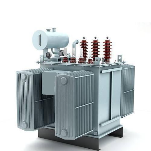
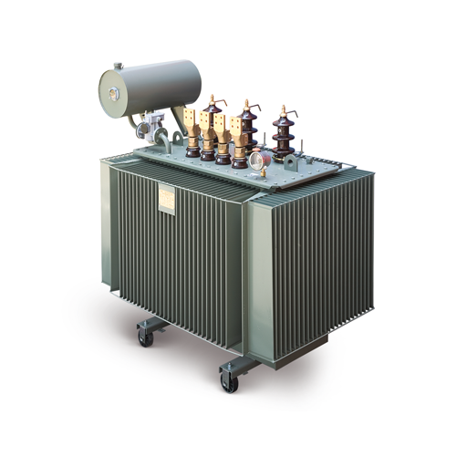
Oil Immersed Distribution Transformers
Oil-cooled distribution transformers are cooled and insulated by mineral oil. The oil flows through the natural convection process, and facilitates the transfer of heat from the core and winding to the tank surfaces and radiators. These units can operate at higher kVA ratings and are deployed out-of-doors with excellent reliability. Oil-based transformers account for approximately 6575% of the installed base in the world. Now, if the oil is given proper testing and maintenance, the service life can be significantly improved.For a deeper look at liquid-filled designs, see our guide to oil immersed transformers.
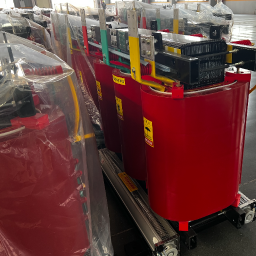
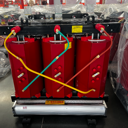
Dry Type Distribution Transformers
Dry type distribution transformers rely on air or cast resin insulation instead of liquid coolant. They are ideal for indoor installations, fire-sensitive environments, and locations where oil containment is impractical. Common applications include hospitals, data centers, high-rise commercial buildings, and underground transit systems. Ratings typically run from 50 kVA to 5,000 kVA. These units require clean, well-ventilated spaces and are more sensitive to dust and moisture than their oil-filled counterparts. For indoor safety-critical projects, dry type transformers are often the required choice.
Single Phase vs Three Phase Distribution Transformers
Single phase distribution transformers serve residential areas and small commercial loads. They are lighter, less expensive, and simpler to install. Three phase distribution transformers power industrial facilities, commercial buildings, and utility distribution networks where motors and large loads require balanced three-phase supply. Most utility and industrial projects specify three phase units because they offer better load balancing, higher efficiency for motor loads, and simpler phase compensation.
Distribution Transformer Ratings and Specifications
Selecting the correct rating and specifications is where most procurement mistakes happen. The following parameters must match the application exactly.
kVA Rating Selection
Common transformer ratings are normally 100 kVA, 250 kVA, 500 kVA, 1000 kVA, 2500 kVA and bigger sizes. Generally speaking, you add up all items connected load in kW, divide by assumed pf of 0.85, and then allow for the “combination” of load diversity factors-2 for this example. Obviously, all loads connected do not operate at the same time. For example, if a building is allowed an 800 kW connected load at 0.7, then the effective load is 560 kW divided by the pf, or about 660 kVA.
Always add a 20–30% margin for future load growth. Transformers are long-life assets, and load profiles grow over decades. Specifying exactly for today’s load guarantees an undersized unit in ten years. However, avoid extreme oversizing. A transformer running below 30% of its rating suffers poor power factor and unnecessarily high no-load losses.
Voltage Ratings
Primary voltage must match the utility supply voltage. Common primary ratings are 6.6 kV, 11 kV, 22 kV, and 33 kV. Secondary voltage must match the facility’s distribution voltage. In most 50 Hz regions, this is 400 V line-to-line and 230 V line-to-neutral. In 60 Hz regions, 480/277 V is common. Special voltages exist for industrial and renewable applications. Verify both primary and secondary requirements with the utility and the facility electrical designer before requesting quotations.
Frequency and Phases
Frequency — 50 Hz or 60 Hz — affects core design, flux density, and no-load loss. A transformer designed for 50 Hz will overheat if operated at 60 Hz at the same voltage, and vice versa. Phase selection follows the load: single phase for small residential and rural applications, three phase for commercial, industrial, and utility networks.
Impedance and Short-Circuit Withstand
Typical impedance for distribution transformers ranges from 4% to 6%. Impedance limits short-circuit current during a fault, protecting downstream equipment and allowing protective relay coordination. Lower impedance reduces voltage drop under load but increases fault current. Higher impedance limits fault current but increases voltage regulation challenges. The right value depends on upstream protection settings and downstream cable ratings.
Distribution Transformer Efficiency and Losses
Efficiency is not a single number. It is a curve that changes with load, and the design goal for distribution transformers is different from any other transformer type.
All-Day Efficiency vs Maximum Efficiency
A power transformer is designed for maximum efficiency at or near full load because it operates there consistently. A distribution transformer is designed for all-day efficiency — the weighted average efficiency across a typical daily load cycle. Because distribution loads vary, the peak efficiency typically occurs at 50–75% of rated load. This is not a compromise. It is the correct optimization for the application.
No-Load Losses
No-load losses, also called core losses or iron losses, occur whenever the transformer is energized. They are caused by hysteresis and eddy currents in the core steel. These losses are essentially constant regardless of how much load is connected. In distribution transformers, no-load losses typically account for 30–50% of total losses. Using high-grade grain-oriented silicon steel and optimized core geometry reduces these losses significantly.
Load Losses
Load losses, also called copper losses or winding losses, vary with the square of the load current. They are caused by resistance in the windings. At 50% load, copper losses are one-quarter of their value at full load. At 100% load, they dominate. The balance between no-load and load loss depends on the expected load profile. A transformer serving a base load with little variation should prioritize low no-load loss. A transformer with high peak-to-average ratio should prioritize low load loss.
Quantified Impact
Consider a 1000 kVA transformer operating at an average 60% load with an electricity cost of 0.12perkWh.A0.50.12perkWh.A0.53,100 per year. Over 25 years, that is more than $77,000 — often exceeding the original purchase price. This is why lifecycle cost, not purchase price, should drive the selection.
For a detailed breakdown of efficiency standards and testing methods, refer to our guide on transformer efficiency.
When Elena, a procurement manager for a Brazilian manufacturing group, compared two 2500 kVA bids, the lower-priced option had 20% higher no-load losses. Over 20 years, the higher-loss unit would cost an additional $48,000 in energy. She chose the higher-efficiency design. The payback period was under four years, and the savings continued for two decades.
Standards and Certifications for Distribution Transformers
Standards compliance is not optional. It determines safety, efficiency, interoperability, and market access. Buyers should verify which standards apply to their region and project.
IEC 60076 Series
IEC 60076 is the international standard for power transformers, including distribution transformers. Part 1 covers general requirements, Part 2 covers temperature rise, Part 3 covers insulation levels and dielectric tests, and Part 7 covers loading guides. IEC compliance is expected in Europe, Africa, most of Asia, the Middle East, and South America.
IEEE C57.12.00 and C57.12.34
In North America, general requirements of liquid-immersed distribution transformers are defined by the IEEE C57.12. 00 standard; liquid-immersed pad-mounted transformers requirements follow under IEEE C57.12. 34. These standards detail temperature rise limitations, insulation levels, method of testing, and construction specifications. Potential buyers in the United States, Canada, and Mexico should demand that IEEE be met.
ANSI C57.12.20
ANSI C57.12.20 specifically covers overhead-type distribution transformers. It defines kVA ratings, voltage ratings, impedance values, and physical dimensions. Specifying ANSI compliance ensures the unit will fit existing pole mounting hardware and meet regional safety expectations.
DOE 2016 Efficiency Requirements
The U.S. Department of Energy established minimum efficiency standards for distribution transformers in 2016. These standards mandate maximum allowable no-load and load losses by kVA rating. Units sold in the United States must comply. Similar regulations exist in Canada under NRCan and in the European Union under Ecodesign Directive 2009/125/EC.
CE Marking and UL Listing
CE marking is essential for electrical transformers introduced to the European market. This marking confirms compliance with the appropriate EU directives, namely, the Low Voltage Directive and RoHS. UL listing is mandated in many jurisdictions in North America, and often, insurance companies demand it whether legislation stipulates it or not.
A credible manufacturer should provide test reports demonstrating compliance with the applicable standards. For large orders, buyers may specify witness tests at the factory.
How to Select a Distribution Transformer for Your Project
The selection process can be organized into five clear steps. Following them reduces specification errors and ensures the transformer fits the project for its full service life.
Step 1 — Define Load Requirements
Calculate the total connected load in kW. Apply a diversity factor based on load type: 0.5 to 0.7 for residential, 0.6 to 0.8 for commercial, and 0.7 to 0.9 for industrial. Convert to kVA using the expected power factor. Add 20–30% for future growth. The result is the minimum kVA rating. Round up to the next standard size, not down.
Step 2 — Choose the Installation Environment
Determine whether the transformer will be installed indoors or outdoors. Outdoor installations in open spaces favor oil immersed units. Indoor installations, fire-sensitive areas, and densely occupied buildings favor dry type units. Consider ambient temperature, altitude, humidity, and pollution level. Standard transformers are rated for altitudes up to 1000 m. Above that, derating is required because air density and cooling efficiency decrease. If your project involves step-down voltage conversion from medium voltage to facility voltage, confirm that the secondary voltage matches your switchgear rating.
Step 3 — Specify Voltage and Configuration
Confirm the primary voltage with the utility or upstream substation designer. Confirm the secondary voltage with the facility electrical designer. Specify the winding connection: Dyn11 is common for mixed commercial and industrial loads because it suppresses third-harmonic currents and provides a stable neutral. Yyn0 is common for residential distribution where neutral current is predictable. For specialized applications, custom configurations are available.
Step 4 — Factor in Efficiency and Lifecycle Cost
Request no-load and load loss data from each bidder. Calculate total cost of ownership over 20–30 years using expected load profile, electricity cost, and discount rate. Do not select on purchase price alone. A transformer with 15% higher upfront cost and 10% lower losses often pays back within five years and generates substantial savings thereafter. This is the core of efficient value: lower lifecycle cost, not lower purchase price.
Step 5 — Verify Standards and Testing
Request routine test reports for the offered design. Confirm compliance with local standards. For orders above a threshold value — typically 50,000to50,000to100,000 depending on buyer policy — specify witness tests for ratio, winding resistance, no-load loss, load loss, and impulse withstand. These tests verify that the manufactured unit matches the design data.
When Ken, a utility buyer in Southeast Asia, followed this five-step process for a 500-unit rural electrification project, he reduced transformer failure rates in the first three years from 4.2% to 0.8%. The difference was not the manufacturer. The difference was correct specification at the procurement stage: proper kVA sizing, Dyn11 winding selection, and factory witness testing.
Installation and Siting Best Practices
Even a perfectly specified transformer can fail if installed incorrectly. The following practices protect performance and safety.
Pad Specifications for Pad Mounted Units
The concrete pad must be level, structurally adequate for the unit weight, and include drainage to prevent water accumulation. Typical pad dimensions extend 150–300 mm beyond the enclosure on all sides. Anchor bolts must align with the transformer base pattern. The pad should be raised 100–200 mm above finished grade to prevent flooding.
Clearance Requirements
Provide sufficient space around the transformer for safety, fire codes, and maintenance access. This very normally required differently by jurisdiction, but a typical set of figures might be 1.0 m from building walls, 3.0 m from building openings, and 0.9 m on the working side for the clear product to pass. Always confirm local electrical, safety and fire codes before finalizing the layout.
Grounding and Bonding
The transformer has to be earthed to the earthing system of the substation. The neutral point should be earthed according to local practice: solidly earthed, resistance earthed, or reactance earthed. An appropriate grounding practice permits limitation of touch potential during a fault and furnishes a path to operate protective relays.
Cable Entry and Termination
Cable entries must never stress bushings or terminal connections. Use cable lugs of the correct size, torque them to the manufacturer specifications, and make sure the cable openings are sealed to keep out moisture and pests. High-voltage terminations always require personnel trained to the specific PPE.
Ventilation for Indoor Dry Type Units
Dry type transformers are required to be ventilated to remove heat. These necessary ventilation openings shall depend upon the losses of the transformer and the geometry of the room. For the most critical installations, high-temperature alarm/tripping contacts are advised.
Environmental Protection
Consider flood risk, corrosive atmospheres, seismic activity, and extreme temperatures. Coastal environments may require stainless steel hardware or special paint systems. Seismic zones require bracing or special tank construction. Cold climates require oil with appropriate pour points or dry type units to avoid gelling.
Maintenance and Reliability
Distribution transformers are designed for long service life, but that life depends on proper maintenance. A well-maintained oil immersed unit can operate 30–40 years. Dry type units in clean environments can achieve similar longevity.
Oil Testing Schedule
For oil-immersed distribution transformers, annual dissolved gas analysis (DGA) is recommended. DGA detect gases generated by overheating, arcing, or partial breakdown within the tank. Early detection allows remedial steps to be taken prior to catastrophic failure. Oil dielectric strength and moisture content should also be monitored annually or biennially.
Thermographic Inspection
Infrared thermography identifies hot spots in connections, bushings, and tap changers. An annual thermographic survey can reveal loose connections or overloaded phases before they cause failure.
Bushing and Connection Checks
Inspect bushings for cracks, tracking, and contamination. Clean bushings annually in polluted environments. Check and retorque bolted connections according to a scheduled maintenance program.
Temperature Monitoring
Install temperature indicators or remote monitors on critical units. Oil temperature and winding temperature indicators provide early warning of overload, cooling system blockage, or ambient temperature excursions.
Common Failure Modes
The most common distribution transformer failure mechanisms are insulation degradation, overheating, and moisture ingress. Insulation deterioration is progressive with thermal aging, the age rate of which doubles for every 6-10 degrees Celsius above the rated temperature. Overheating results from overload and can be caused by poor ventilation and high ambient temperatures. Moisture penetrates the system through failed gaskets or seals, decreasing oil dielectric strength and enhancing paper insulation oxidation. The best care plan must address all three mechanisms.
Distribution Transformers for Renewable Energy
Renewable energy projects place unique demands on distribution transformers. Solar farms, wind farms, and battery energy storage systems require designs that differ from standard utility applications.
Solar Farm Applications
In utility-scale solar installations, distribution transformers step down from the medium-voltage collector system — typically 33 kV — to the grid interconnection voltage. Solar transformers must handle bidirectional power flow, tolerate harmonic currents from inverters, and operate efficiently at partial load because solar output varies with weather and time of day. Low no-load losses are especially valuable because inverters may be offline at night while the transformer remains energized.
Wind Farm Collector Systems
Wind turbines generate at low voltage, which is stepped up to medium voltage by turbine transformers. The collector system then aggregates multiple turbines before the main substation transformer steps up to transmission voltage. Turbine transformers in nacelles or at tower base are specialized distribution transformers that must withstand vibration, temperature cycling, and limited maintenance access.
Battery Energy Storage System Integration
BESS installations require transformers that can handle rapid charge and discharge cycles. The transformer must tolerate frequent thermal cycling, harmonic content from power conversion systems, and occasional reverse power flow. These applications often specify lower flux density to reduce core losses and audible noise.
Key Takeaways and Procurement Checklist
Before issuing a request for quotation or placing an order, verify the following:
- kVA rating calculated with diversity factor and 20–30% growth margin
- Primary and secondary voltages confirmed with utility and facility designers
- Winding connection selected for load type and harmonic environment
- Cooling type matched to installation environment and safety requirements
- Impedance coordinated with upstream and downstream protection
- Efficiency evaluated on total cost of ownership, not purchase price alone
- Standards compliance verified for target market and local regulations
- Test requirements specified — routine reports for all units, witness tests for large orders
- Installation conditions reviewed: pad specs, clearances, grounding, ventilation
- Maintenance plan established: oil testing, thermography, connection checks
Ready to move forward? Send your load profile, voltage requirements, and installation details to Shandong Electric Co., Ltd. for a custom specification review and quotation.
Conclusion
A distribution transformer stands out as a long-term asset that will impact safety, efficiency, and operational cost over a span of decades. The right distribution transformer, adequately specified and properly maintained, can result in 25 to 40 years of steady performance. The wrong transformer that has been incorrectly matched will become an unforeseen source representing cost followed by downtime.
The specifications process is not complicated; however, it calls for minute attention. Careful load calculations are necessary; provide an overhead in the growth margin; make the cooling means matched with the environment; compare the lifespan of all bidders; ensure strict compliance with the standards; and, most importantly, have in place from Day One an annual maintenance plan.
If you are evaluating distribution transformers for a utility, industrial, or renewable energy project, our engineering team can review your specifications and recommend the most practical configuration. Contact us with your requirements.