Transformer for Solar Plant: Sizing, Selection, and Standards Guide
A transformer for solar plant applications is not a standard distribution transformer with a new label. Solar farms require specially specified units that handle inverter harmonics, tolerate highly variable load cycles, and remain energized through long no-production periods. Get the specification wrong, and the unit will waste energy, overheat, or fail prematurely.
Most solar EPCs and developers treat transformers as a commodity. They copy specifications from previous projects or let the inverter vendor choose. The result is predictable. Inverter harmonics overload standard windings. No-load losses erode revenue during nights and cloudy days. Impedance mismatches trigger nuisance tripping at the grid interconnection point. These problems are expensive to fix after installation and almost always preventable at the specification stage.
This guide covers exactly how to size, specify, and procure transformers for solar power plants. You will learn the three transformer roles in a solar farm, how to calculate kVA ratings with worked examples, why loss economics differ from conventional applications, and which standards govern your selection. Whether you are developing a 1 MW commercial rooftop system or a 100 MW utility-scale farm, the principles are the same.
Key Takeaways
- Solar farms use three distinct transformer types: inverter transformers, collector system transformers, and substation interconnection transformers. Each has a different sizing method.
- Standard distribution transformers often fail in solar applications because modern inverters generate harmonic currents that require K-factor 4, 13, or 20 rated windings.
- No-load losses matter more in solar than in conventional applications because the transformer stays energized 24/7 while the plant produces energy only 20–25% of the year.
- Sizing must include a 10–15% overload margin to handle cloud-edge transients and DC/AC ratio oversizing.
- IEEE 1547 and IEC 61727 set interconnection requirements that directly affect transformer impedance, voltage regulation, and grounding specifications.
How Transformers Fit Into Solar Power Plant Architecture
Understanding where transformers sit in the power flow is the first step to correct specification. A utility-scale solar farm is not one big inverter connected to one big transformer. It is a staged voltage elevation system with multiple transformer roles.
The Three Transformer Roles in a Solar Farm
Inverter transformers step up from the inverter output voltage — typically 400 V or 480 V AC — to the medium-voltage collector system, usually 11 kV, 22 kV, or 33 kV. In a central inverter architecture, each inverter block has a dedicated transformer. In a string inverter design, multiple inverters may feed a single pad-mounted unit.
Collector system transformers aggregate power from multiple inverter transformers. In large plants, the collector system operates at 33 kV and feeds a central substation. The collector transformer steps up or matches voltage to the substation bus level.
Substation or grid interconnection transformers perform the final voltage step-up from the collector system to the transmission grid voltage. This may be 66 kV, 110 kV, or higher depending on the grid connection agreement. For a deeper look at how voltage step-up works in renewable projects, see our guide on step up transformer vs step down transformer applications.
Central Inverter vs String Inverter Architecture
Central inverters — typically 1 MW to 6.25 MW each — require larger individual transformers. The transformer sits outdoors next to the inverter block. String inverters — typically 50 kW to 250 kW each — use smaller pad mounted transformers that aggregate dozens of inverter strings. The choice affects transformer count, sizing, and maintenance access.
When Linh, an EPC contractor in Vietnam, designed a 50 MW central inverter plant, she specified standard distribution transformers for the inverter blocks. The inverters generated total harmonic distortion of 4.5%, which the standard units were not designed to handle. Within 18 months, neutral conductors overheated and insulation degraded prematurely. The fix required replacing twelve inverter transformers with K-factor 13 designs. The cost of replacement, re-installation, and lost production exceeded 180,000.A180,000.A4,000 specification upgrade at procurement would have prevented it entirely.
Need guidance on transformer architecture for your solar project? Contact our engineering team to review your single-line diagram and recommend the right configuration.
Transformer Types Used in Solar Applications
The environment and scale of the solar project determine which transformer type is appropriate. There is no universal answer.
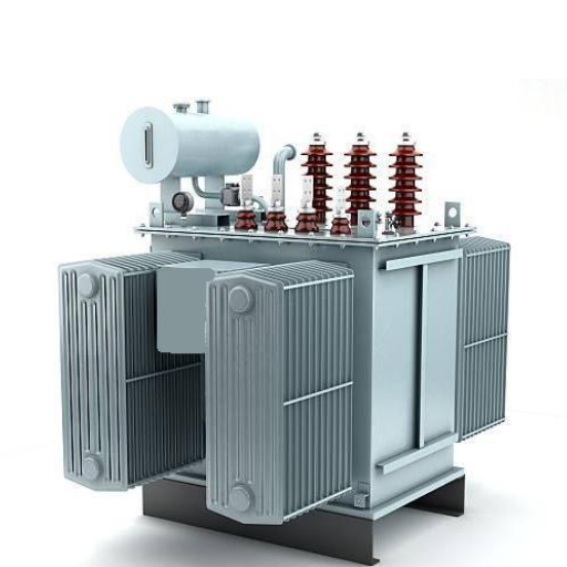
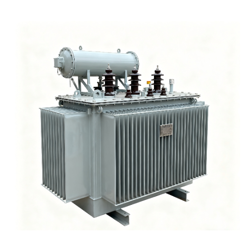
Oil Immersed Transformers for Utility-Scale Solar
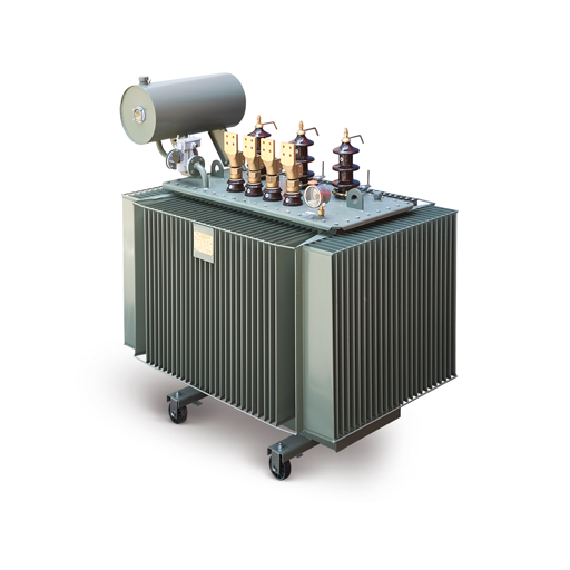
Oil immersed transformers dominate utility-scale solar because they handle higher kVA ratings, tolerate outdoor temperature extremes, and cost less per kVA than dry type alternatives. For collector systems, pad-mounted enclosed designs provide security and weather protection. For substation interconnection, larger power transformers with radiator cooling or forced oil circulation are standard.
The outdoor rating of oil immersed units is a significant advantage in solar applications. Solar farms are, by definition, built on open land with full sun exposure. Ambient temperatures at the transformer location often exceed 40 degrees Celsius. Oil cooling handles these conditions reliably. For projects considering outdoor pad mounted transformer installations, oil-filled designs are the practical choice.
Dry Type Transformers for Solar Applications
Dry type transformers are preferred for indoor inverter rooms, containerized inverter stations, and building-integrated photovoltaic systems where fire safety codes prohibit liquid-filled equipment. They eliminate oil spill risk and require no fire-suppression infrastructure. The trade-off is higher upfront cost and lower thermal capacity for the same footprint.
In commercial rooftop and carport solar installations, dry type units are often the only option permitted inside the building electrical room. They also make sense in environmentally sensitive areas where oil containment is difficult or regulated.
Step-Up Transformers in Solar Farms
Solar farms are fundamentally step-up applications. The DC power from photovoltaic panels is converted to AC by inverters at low voltage. Step up transformers raise this voltage through two or three stages before it reaches the transmission grid.
Typical voltage ratios are 400/11 kV, 400/33 kV, or 33/132 kV depending on the plant scale and grid requirements. Tap changers are often specified with a wider range than standard industrial transformers because grid codes require voltage regulation capability across varying solar output and grid conditions.
K-Factor and Harmonic-Rated Transformers
This is the specification detail that separates solar transformers from standard units. Modern string inverters and central inverters both generate harmonic currents. Total harmonic distortion of current (THDi) typically ranges from 2% to 6% depending on inverter topology and filter design.
Standard transformers are designed for sinusoidal loads. Harmonics cause additional heating in windings and neutral conductors that standard temperature rise calculations do not account for. The result is premature insulation aging, neutral overheating, and reduced service life.
K-factor ratings quantify a transformer’s ability to handle harmonic loads. K-4 suits older inverters with THDi below 3%. K-13 is appropriate for modern string inverters with THDi of 3–5%. K-20 may be required for plants with poor power factor or mixed inverter technologies. Specifying K-13 for a utility-scale project is now standard practice. It adds 10–20% to the transformer price and can prevent $100,000+ in replacement costs.
How to Size a Transformer for a Solar Plant
Sizing solar transformers requires a different approach than sizing industrial or utility distribution transformers. Solar load profiles are predictable in annual energy but highly variable in instantaneous output.
Sizing the Inverter Transformer
The inverter transformer must handle the inverter AC output at full power with margin for overload conditions. The basic formula is:
Inverter transformer kVA = (Inverter AC power output in kW x Number of inverters) / Power factor x Overload margin
For modern inverters, the power factor is typically 0.99 or unity. The overload margin accounts for cloud-edge effects, DC/AC ratio oversizing, and transient conditions. A margin of 1.10 to 1.15 is standard.
Worked example: A 10 MW plant uses four 2.5 MW central inverters. Each inverter outputs 2,500 kW at unity power factor. With a 1.10 overload margin:
Inverter transformer kVA = 2,500 kW x 4 / 0.99 x 1.10 = 11,111 kVA
Round up to the next standard size: 12,500 kVA or split into two 6,250 kVA units depending on redundancy requirements.
The DC/AC ratio also matters. Many plants oversize the DC array relative to the inverter AC rating to improve capacity factor. A DC/AC ratio of 1.3 means the DC array can deliver 130% of the inverter rating under ideal conditions. The inverter clips the output, but the transformer must handle the inverter’s full AC nameplate continuously.
Sizing the Collector System Transformer
The collector system transformer aggregates multiple inverter transformers. Unlike industrial applications, solar plants have a diversity factor of approximately 1.0. All inverters peak simultaneously when the sun is bright. There is no diversity benefit.
Collector transformer kVA = Sum of all inverter transformer ratings x 1.05 auxiliary load margin
For the 10 MW example above with four 2.5 MW inverters aggregated at 33 kV, the collector transformer would be sized at approximately 11,500 kVA to 12,500 kVA.
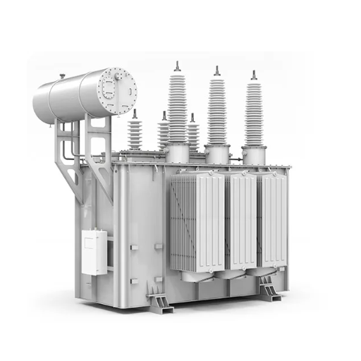
Sizing the Grid Interconnection Transformer
The substation transformer must handle the full plant output plus auxiliary loads such as control systems, cooling, and lighting. It must also accommodate future expansion if the site is phased.
Substation transformer MVA = (Plant MW rating + Auxiliary load MW) / Power factor x Future margin
Worked example: A 50 MW plant with 0.5 MW auxiliary load and 1.20 future expansion margin:
Substation transformer MVA = (50 + 0.5) / 0.99 x 1.20 = 61.2 MVA
Round to the next standard size: 63 MVA or 75 MVA depending on utility requirements.
When James, a project engineer in Kenya, sized the collector transformer for a 10 MW plant, he matched it exactly to the inverter nameplate total with zero margin. During commissioning, a cloud-edge transient caused all four inverter blocks to peak simultaneously for several minutes. The transformer hit 108% of rated load and the temperature alarm triggered. He had to order an emergency replacement sized 15% larger, delaying commercial operation by six weeks. The lesson: solar inverters do not behave like diversified industrial loads. Add margin.
Voltage Ratio and Tap Changer Selection
Grid interconnection agreements specify the exact voltage and regulation requirements. Tap changers are typically specified with +/- 10% in 1.25% steps to maintain voltage within the utility’s acceptable band. Confirm the grid voltage and tap range with the utility interconnection engineer before requesting quotations.
Sizing Summary by Plant Scale
| Plant Capacity | Inverter Transformer | Collector Transformer | Substation Transformer | Typical MV Level |
|---|---|---|---|---|
| 1 MW | 1 x 1,250 kVA | 1 x 1,250 kVA | 1 x 1,600 kVA | 11 kV |
| 10 MW | 4 x 3,150 kVA | 1 x 12,500 kVA | 1 x 16 MVA | 33 kV |
| 50 MW | 8 x 6,250 kVA | 2 x 25 MVA | 1 x 63 MVA | 33/66 kV |
| 100 MW | 16 x 6,250 kVA | 4 x 25 MVA | 1 x 125 MVA | 66/110 kV |
Transformer Losses and Solar Plant Economics
Loss economics in solar applications differ fundamentally from industrial or utility applications. Understanding why will save money over the plant’s 25-year life.
Why No-Load Loss Matters More in Solar
A typical utility-scale solar plant operates at rated output only 20–25% of the year. The remaining 75–80% of the time, output is below rated capacity or zero. Yet the transformer remains energized continuously. It consumes no-load losses — also called core losses or iron losses — every hour of every day.
No-load losses are independent of load. A 1000 kVA transformer with 1.5 kW no-load loss consumes 1.5 kW whether the plant is generating 100% capacity or zero. Over a year, that is 13,140 kWh of wasted energy. At 0.08perkWh,theannualcostis0.08perkWh,theannualcostis1,051. Over 25 years, discounted at 5%, the present value of those losses exceeds $14,800. That is often more than the purchase price of the transformer itself.
For a detailed breakdown of loss types and efficiency testing, refer to our guide on transformer efficiency.
Load Losses at Part-Load Operation
Load losses vary with the square of the load current. At 50% output, load losses are 25% of full-load value. At 25% output, they are 6.25%. Because solar plants spend most of their operating hours below full load, average load losses are modest. The dominant loss factor for solar duty cycles is no-load loss, not load loss.
Total Cost of Ownership
The correct economic comparison is total cost of ownership over the plant life:
TCO = Purchase price + PV(no-load losses) + PV(load losses) + Maintenance
Premium efficiency transformers with low-loss core steel may cost 15–25% more upfront. The payback period is typically 4–7 years. The savings continue for the remaining 18–21 years of plant life.
When Carolina, a developer in Chile, commissioned an 80 MW plant, she chose standard-efficiency substation transformers to save 18,000perunitontheinitialpurchase.AfterYear2,anindependentenergyauditrevealedthateachunitwaswasting18,000perunitontheinitialpurchase.AfterYear2,anindependentenergyauditrevealedthateachunitwaswasting6,200 per year in excess no-load losses compared to the premium efficiency alternative. Over 20 years, the total excess cost per unit would exceed 77,000.Retrofitwasnoteconomicalbecauseitrequiredsubstationshutdownandcranerental.Theinitial77,000.Retrofitwasnoteconomicalbecauseitrequiredsubstationshutdownandcranerental.Theinitial18,000 savings became a $77,000 liability. Specify low-loss designs at procurement.
Ready to optimize transformer losses for your solar project? Send your plant capacity, voltage requirements, and duty cycle to Shandong Electric Co., Ltd. for a TCO comparison of standard and premium efficiency designs.
Standards and Grid Code Requirements
Solar transformers must comply with both general transformer standards and renewable energy interconnection standards. The combination creates requirements that standard industrial transformers may not satisfy.
IEEE 1547 and Interconnection Standards
IEEE 1547-2018 establishes the interconnection and interoperability standards for distributed energy systems that operate throughout North America. The requirements include voltage regulation and ride-through specifications and power quality restrictions which impact the design of transformers.
The plant’s reactive power capacity needs to be matched with the transformer impedance requirements. The transformer impedance must remain below a specific threshold which enables effective voltage regulation at the point of interconnection when the inverter needs to provide voltage support through reactive power injection. Solar interconnection transformers typically have an impedance range between 6% and 10% which exceeds the impedance of standard industrial transformers.
IEC 61727 and IEC 60076 Applicability
Outside North America, IEC 61727 defines the characteristics of the utility interface for photovoltaic systems. It specifies harmonic current injection limits, voltage deviation limits, and power factor requirements. The transformer must be tested to IEC 60076 standards with additional consideration for the harmonic content specified in IEC 61727.
Type test reports should demonstrate compliance with both IEC 60076-1 general requirements and the specific harmonic withstand capability for solar applications.
Local Grid Code Considerations
Every utility has its own grid code that adds requirements beyond international standards. Common additional requirements include:
- Impedance limitations: Some utilities cap transformer impedance to ensure fault current levels remain within switchgear ratings.
- Grounding requirements: Solid grounding, resistance grounding, or reactance grounding may be specified depending on the utility’s protection philosophy.
- Reactive power capability: The transformer may need to be oversized to handle reactive power flow in addition to real power.
Always request the utility’s interconnection requirements document before finalizing transformer specifications.
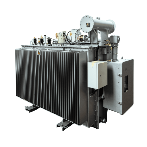
Installation and Environmental Considerations
Solar farms are installed in harsh environments. Desert heat, coastal salt, high altitude, and dust all affect transformer selection and performance.
Outdoor vs Indoor Installation
Outdoor installation is standard for utility-scale solar. Oil immersed units with UV-resistant paint and sealed enclosures handle sun exposure and temperature cycling. For sites above 1000 meters altitude, derating is required because air density decreases and cooling efficiency drops. A typical rule is 0.5% derating per 100 meters above 1000 meters.
Coastal sites require corrosion protection. Stainless steel hardware, special paint systems, or tropicalized designs prevent salt-induced degradation. Desert sites require high-temperature performance and dust filtration on breathing systems.
Pad Specifications for Pad-Mounted Solar Transformers
Pad-mounted transformers for solar collector systems require concrete pads that extend at least 150 mm beyond the enclosure on all sides. The pad needs to be level while its design should include drainage systems that prevent water accumulation. The pad layout requires cable trenches to integrate with their design in order to prevent sharp cable bends.
Oil Containment and Environmental Protection
In the United States, the EPA Spill Prevention, Control, and Countermeasure rule applies to oil-filled transformers with aggregate capacity above threshold levels. The situation requires either containment structures or oil-water separators to be installed. Synthetic ester fluids provide an environmentally friendly substitute to mineral oil which helps to ease environmental permit processes in protected areas.
Procurement Checklist for Solar Transformers
Use this checklist before requesting quotations or evaluating bids:
- kVA or MVA rating calculated with 1.10–1.15 overload margin for inverter transformers
- Primary and secondary voltages confirmed with inverter vendor and utility interconnection engineer
- K-factor rating specified based on inverter THDi — K-13 minimum for modern inverters
- Impedance coordinated with utility protection settings and reactive power requirements
- Tap changer range matching grid code voltage regulation requirements
- Cooling type selected for installation environment — oil immersed for outdoor, dry type for indoor
- No-load and load loss values provided by bidder for TCO comparison
- Standards compliance — IEC 60076, IEEE C57.12.00, or ANSI C57.12.00 as applicable
- Temperature rise rated for site ambient conditions including altitude derating
- Noise level confirmed for sites near residential or noise-sensitive areas
- Factory testing specified — routine tests for all units, witness tests for substation transformers
- Delivery schedule aligned with project construction timeline
Send this checklist to each bidder and compare responses line by line. The lowest purchase price is rarely the lowest total cost.
Conclusion
A transformer for solar plant projects is a specialized asset, not a commodity. The combination of inverter harmonics, highly variable load cycles, and 24/7 energization creates requirements that standard distribution transformers are not designed to meet.
The three critical specification decisions are: sizing with proper overload margin, selecting the correct K-factor rating for harmonic tolerance, and evaluating bids on total cost of ownership rather than purchase price alone. Each of these decisions is made once at procurement and affects performance for 25 years.
If you are developing a solar farm and need transformers sized to your exact inverter layout, voltage requirements, and grid code, our engineering team can review your specifications and recommend the most practical configuration. Contact us with your project details.