

BESS Transformer Sizing: Matching PCS kVA and Operating Requirements

BESS transformer sizing starts with the maximum simultaneous active and reactive power crossing a defined AC boundary. Calculate each permitted operating case, check that the power conversion system (PCS) can deliver it, and have the transformer supplier validate the rating for the actual site and duty.
A battery energy storage system’s MWh capacity describes stored energy. It does not, by itself, establish the transformer kVA requirement. A useful sizing worksheet connects the single-line drawing, PCS capability data, auxiliary supply routes and grid requirements to one consistent set of operating cases.
For the wider equipment and interface decisions, start with our guide to BESS transformer selection and interfaces. This article develops the numerical loading method.
Key takeaways
- Calculate P and Q together for each operating case before comparing kVA requirements.
- Check charging, discharging and any required reactive-support modes separately.
- Include auxiliaries only where their supply path crosses the transformer being assessed.
- Verify PCS capability and transformer site rating independently.
- Use the calculation as a documented input to equipment selection, with thermal and waveform review still required.
Define the AC boundary before calculating capacity
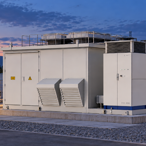
Identify the PCS block and grid connection
Mark the transformer and winding being assessed on the single-line drawing. A block transformer serving one PCS group has a different loading boundary from a collector transformer serving several groups. The grid’s point of interconnection (POI) may be farther upstream.
The following conceptual arrangement shows auxiliaries connected to the same low-voltage (LV) bus as the PCS. Arrows indicate bidirectional power paths; the arrangement is illustrative, not a prescribed system architecture.
Battery DC <-> PCS <-> LV bus <-> Block transformer <-> MV collector <-> POI/grid
                         |
                         +--> Auxiliary loads
At the transformer’s LV connection, calculate the combined PCS and auxiliary flow. For a requirement specified at the POI, the grid engineer must also account for the intervening equipment’s active and reactive effects. Do not treat a POI power-factor requirement as an unchanged PCS-terminal requirement.
Package names alone do not establish these boundaries. In its November 26, 2025 announcement, SMA described a 40-ft package containing two inverters, two transformers and medium-voltage switchgear. This is an example of component grouping, not a rating template for another project.
Prepare a controlled input sheet
Record the document revision beside every material input. The worksheet should identify:
| Input | What to establish |
|---|---|
| PCS arrangement | Unit count, AC connection points, continuous and temporary ratings |
| Capability | Permitted simultaneous P-Q combinations over voltage, temperature and DC operating range |
| Electrical boundary | Winding voltage range, auxiliary branches and POI location |
| Service obligations | Import, export, reactive support, duration and permitted curtailment |
| Installation | Ambient conditions, altitude, enclosure, ventilation and cooling arrangement |
| Future operation | Approved expansion and any required reduced-equipment operating cases |
If you are preparing an inquiry, send the single-line drawing and available PCS data with your operating requirements. Identify missing inputs explicitly so that a preliminary estimate is not mistaken for an approved equipment rating.
Convert BESS operating requirements into kVA and current
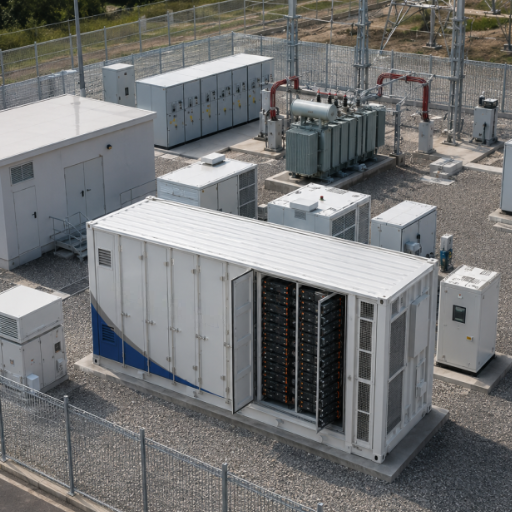
Separate MW, MWh and apparent power
MW describes active power at a stated location. MWh describes energy and helps define how long a battery can sustain a duty. kVA or MVA describes apparent power and is central to the transformer loading calculation; our transformer kVA and MVA ratings guide explains the general terminology.
For sinusoidal steady-state conditions, use:
S (kVA) = sqrt[P (kW)² + Q (kvar)²]
Here, P is active power and Q is reactive power at the same boundary and operating point. Schneider Electric’s reactive-power explanation establishes the sinusoidal power-vector relationship behind this equation. With converter waveforms, this calculation alone does not establish total RMS current or harmonic heating suitability.
If active power and a nonzero power-factor magnitude are specified instead, use:
S (kVA) = |P (kW)| / |PF|
Schneider Electric defines power factor as the ratio of active to apparent power. Use magnitudes when calculating the required kVA for import or export. At zero active power, enter the required Q directly; a power-factor target alone cannot describe the required amount of reactive support.
Sum coincident flows before calculating kVA
Use one sign convention throughout the worksheet. For example, define grid import as positive P and reactive import as positive Q. Then sum all simultaneous P contributions and all simultaneous Q contributions crossing the selected connection.
Calculate apparent power from those two totals. Adding separate equipment kVA magnitudes can obscure the actual combined P-Q requirement. Equally, combining maximum P from one mode with maximum Q from an incompatible mode invents a duty that may never be required.
List the actual permitted combinations, including any enforced restrictions. A restriction should be a documented operating condition with a responsible control or protection function, not an assumed diversity credit.
Check current at the winding voltage
For balanced three-phase operation:
I (A) = 1,000 × S (kVA) / [sqrt(3) × V_LL (V)]
V_LL is the line-to-line voltage at the winding being assessed. Schneider Electric’s installed apparent power guidance gives the three-phase relationship. Keep kVA, volts and amperes consistent; using kV in this expression without changing the conversion factor produces an incorrect result.
Check the required operating voltage range with the supplier. This current calculation is a loading check, not a cable-sizing, short-circuit or protection-coordination design.
Compare charging, discharging and reactive-support duty
Charging and discharging are separate operating cases at a bidirectional PCS interface. Do not add their MW magnitudes together as though they occur simultaneously through the same converter. Within each case, however, include all simultaneous loads and generation that cross the selected transformer boundary.
Build the case schedule before selecting the largest result:
| Case | Quantities to enter | Confirmation needed |
|---|---|---|
| Full discharge/export | Signed PCS P/Q and coincident auxiliaries | Export obligation, reference location and duration |
| Full charge/import | Signed PCS P/Q and coincident auxiliaries | Charging limit, auxiliary demand and duration |
| Energized standby/reactive support | Required Q, PCS active consumption and auxiliaries | Availability of that mode and its continuous limits |
| Shared solar/storage, if applicable | Simultaneous PV, storage and auxiliary P/Q | Allowed combinations and enforced operating limits |
| Reduced-equipment or emergency duty, if required | Remaining equipment and required service | Permitted curtailment, cooling state and duration |
For every row, retain net boundary P/Q, calculated kVA/current, the voltage used, PCS feasibility and the transformer rating conditions. Where duration or cooling state is unknown, enter “project input required.” An incomplete input is more useful than a fabricated operating assumption.
For a shared PV and storage connection, consult the solar plant transformer guide for the solar interface. Then add the permitted storage cases at the shared boundary. Do not assume solar output and battery charging always cancel or that full output is available after equipment is removed from service.
Worked example: BESS transformer sizing with shared auxiliaries
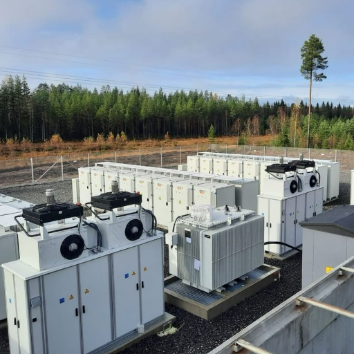
State the assumptions
Illustrative scenario: One hypothetical PCS block connects to a transformer LV bus with 50 kW of auxiliary load. Assume balanced sinusoidal steady state and zero auxiliary reactive demand for simplicity. Positive P means import from the grid; positive Q means reactive import.
The PCS active-power cases are ±2,000 kW with +600 kvar. The reactive-support case requests zero PCS active power and +600 kvar. Actual PCS consumption in that mode would need to be obtained for a real design; the simplified example assigns it zero.
The table excludes transformer and collector losses and their reactive requirements because it describes the LV boundary. Durations and cooling conditions remain project inputs. None of these values describes a customer installation or a selected product.
Calculate the three operating cases
All auxiliary demand in this example crosses the same transformer connection.
| Case | PCS P, kW | PCS Q, kvar | Aux P/Q, kW/kvar | Net P, kW | Net Q, kvar | Boundary S, kVA |
|---|---|---|---|---|---|---|
| Discharge/export | -2,000 | +600 | +50 / 0 | -1,950 | +600 | 2,040.22 |
| Charge/import | +2,000 | +600 | +50 / 0 | +2,050 | +600 | 2,136.00 |
| Reactive-only PCS support | 0 | +600 | +50 / 0 | +50 | +600 | 602.08 |
For the charging case:
S = sqrt(2,050² + 600²) = 2,136.00 kVA
At a hypothetical LV line-to-line voltage of 690 V:
I = 1,000 × 2,136.000936 / [sqrt(3) × 690] = 1,787.28 A
Charging governs this example’s preliminary steady-state demand. During export, the auxiliaries consume part of the PCS output locally; during import, their demand adds to charging power. That difference follows from the stated supply path and signs, not from a universal rule that charging always governs.
The example’s remaining checks are deliberately open:
| Item | Discharge | Charge | Reactive support |
|---|---|---|---|
| Duration | Project input required | Project input required | Project input required |
| PCS feasibility | Confirm P/Q combination | Confirm P/Q combination | Confirm mode and limits |
| Transformer site rating | Supplier confirmation required | Supplier confirmation required | Supplier confirmation required |
| Waveform and thermal assessment | Required | Required | Required |
Check PCS capability separately
In either active-power case, the PCS itself must accommodate:
S_PCS = sqrt(2,000² + 600²) = 2,088.06 kVA
A PCS limited to 2,000 kVA cannot deliver that simultaneous combination under these assumptions. Buying a transformer with a larger kVA rating does not increase the PCS capability. Obtain an approved P-Q envelope rather than assuming that independently listed maximum kW and kvar are available together.
Also distinguish PCS export from POI export. Here, a 2,000 kW PCS export becomes 1,950 kW at the LV transformer connection before upstream losses. A requirement to export 2,000 kW at the POI therefore needs a different power balance.
The 2,136.00 kVA result does not select a final nameplate rating. Winding duties, site conditions, voltage range and thermal assessment remain to be resolved. Increasing battery MWh while keeping these AC cases unchanged leaves the arithmetic unchanged, but a longer operating duty can change the thermal assessment.
Validate PCS and transformer ratings under actual conditions
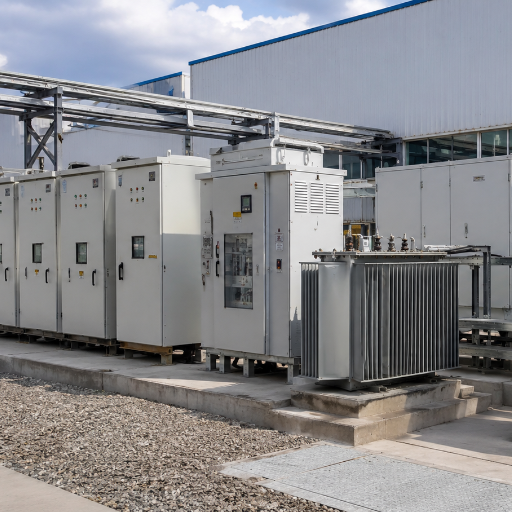
Read the conditions behind the PCS number
PCS ratings can depend on the conditions stated in the datasheet. For example, page 2 of SMA’s Sunny Central Storage UP datasheet, revision SCS-UP-DS-en-23 lists the SCS 3450 UP at 3,450, 3,140 and 2,930 kVA at 25, 40 and 50°C respectively, at 1,200 V DC.
Those values apply to that model and stated conditions. They are not a derating curve for another PCS or for its transformer. Obtain project-specific confirmation across the required AC voltage, DC voltage, temperature and operating-mode range, including simultaneous active and reactive capability.
Confirm the transformer’s thermal and waveform basis
Ask the transformer supplier to assess the approved operating schedule, ambient conditions, altitude, enclosure and cooling arrangement. Distinguish continuous duty from any permitted temporary overload. A temporary rating should include its duration, starting conditions and operating limits.
Hitachi Energy’s solar and BESS transformer guidance identifies cyclic loading, harmonics and converter switching as design considerations. Supply the relevant PCS waveform and operating data for the transformer designer’s assessment. A fundamental-frequency P-Q calculation is an input to that review, rather than a replacement for it.
Avoid inserting a standard percentage margin, auxiliary allowance or harmonic derating factor without a documented basis. Specify any planned expansion as an actual future duty. This keeps the selected rating traceable to an operating requirement.
Evaluate proposals below total PCS nameplate capacity
A proposed transformer rating below the sum of installed PCS ratings needs a clear explanation of the allowed loading. Ask which operating limits prevent excessive transformer duty and how those limits remain effective in the required control and contingency states.
Have the responsible engineers validate the control, protection and loading studies. If a new service or future expansion removes a restriction, reassess the transformer requirement before enabling that duty. A lower rating is not permission to exceed the transformer’s validated operating limits.
Turn the sizing worksheet into a supplier review package
Submit the single-line drawing, operating-case table and PCS capability documents together. Include winding voltages and ranges, site and cooling conditions, auxiliary supply routes, applicable grid requirements and approved future expansion. Each document should carry its current revision.
Ask bidders to identify the continuous rating basis, accepted operating cases, temporary limits and exclusions. Require separate confirmation of PCS feasibility and transformer suitability so that neither is inferred from the other. Where equipment sits inside a container substation, identify the package boundaries and cooling assumptions as well.
Keep the result usable: one stated electrical boundary, one consistent sign convention and a traceable set of permitted duties. For a BESS transformer sizing inquiry, send us your drawing, PCS datasheet and operating-case worksheet, identifying the requirements that still need confirmation.
Does battery MWh determine transformer size?
No. Use AC power and reactive requirements to calculate loading. MWh helps establish operating duration, which must be considered in the thermal review.
Should charging and discharging power be added?
No, when they are mutually exclusive cases through the same PCS interface. Calculate each case separately, including its simultaneous auxiliaries and other flows, then compare the resulting requirements.
Does a larger transformer provide more PCS reactive capability?
No. The requested P-Q combination must remain inside the PCS capability envelope. A larger transformer cannot supply missing converter capability.
Can the transformer be smaller than installed PCS capacity?
Possibly, where documented operating limits and project studies support it. Confirm those limits, the required service and the transformer rating conditions before accepting the proposal.