Dry Type Transformer Installation: Clearances, Mounting & Commissioning Guide
Dry type transformer installation requires proper foundation preparation, adequate clearances per IEC or NEC standards, correct lifting and handling, secure mounting, proper electrical connections, grounding, ventilation, and pre-energization testing before commissioning. Getting any of these steps wrong can lead to overheating, premature failure, or safety violations.
A 2,000 kVA transformer installed with only 200 mm side clearance instead of the required 600 mm overheated within 18 months, requiring a $15,000 emergency relocation. The contractor had tried to save space in a crowded electrical room. The result was a thermal runaway that discolored cable insulation and forced an unplanned shutdown.
This guide covers complete dry type transformer installation from receiving to commissioning. You will find actual clearance dimensions, room layout examples, ventilation calculations, a commissioning checklist, and the most common mistakes contractors make, with specific guidance on how to avoid them.Want the complete picture of all dry type transformer types? See our dry type transformer guide covering cast resin, VPI, and open ventilated designs.
Key Takeaways
- Dry type transformer installation requires minimum 600-1,000 mm clearances depending on rating and local code.
- Room ventilation must remove transformer heat load; inadequate airflow reduces life by approximately 5% per degree C above design ambient.
- Pre-energization testing should include insulation resistance, turns ratio, winding resistance, and partial discharge measurement.
- A poured concrete foundation or steel frame mount must support 2-4x the transformer weight with level tolerance of 2 mm per meter.
- Common installation mistakes include insufficient clearance, inadequate ventilation, improper lifting, and skipped pre-energization tests.
Need help sizing your transformer before installation? See our dry type transformer sizing guide for capacity calculations and selection methodology.
Pre-Installation Preparation and Inspection
Receiving and Storage Procedures
When a dry type transformer arrives on site, inspect the shipment immediately. Check for visible damage to crates, enclosures, or bushings. Review the packing list against the bill of lading. Verify that the nameplate data matches the purchase specification: kVA rating, voltage ratio, vector group, impedance, and tap range.
If installation is delayed, store the transformer in a dry, covered location. Do not store outdoors under tarps. Moisture ingress during storage is one of the most common causes of early failure. The unit should remain in its shipping crate with desiccant packs intact until the day of installation. If outdoor storage is unavoidable, use a climate-controlled temporary shelter rather than a tarp.
Pre-Installation Inspection Checklist
Before moving the transformer to its final location, perform these checks:
- Verify nameplate data against specifications
- Inspect for shipping damage to enclosure, bushings, and terminals
- Check that all accessories (temperature monitors, fans, CTs) are included
- Review factory test reports: ratio, resistance, insulation, and partial discharge
- Confirm tap changer position matches the desired setting
- Photograph the unit condition for warranty documentation
Tools and Equipment Required
A typical dry type transformer installation requires:
- Forklift or crane with rated capacity exceeding unit weight
- Rigging slings and spreader bars
- Torque wrench for electrical connections
- Insulation resistance tester (megger), 1,000 V or 2,500 V
- Turns ratio tester (TTR)
- Winding resistance meter
- Digital multimeter
- Level and straightedge for foundation verification
- Drill and anchor bolts for seismic mounting
Coordination with Utility and Authority Having Jurisdiction
Coordinate with the utility for primary energization scheduling. Some utilities require witness testing before connection. Submit electrical permits and inspection requests to the Authority Having Jurisdiction (AHJ) well in advance. In many jurisdictions, the electrical inspector must approve installation before the unit can be energized.
Transformer Room Design and Clearance Requirements
Minimum Clearances per IEC 61936-1
IEC 61936-1 specifies minimum clearances for power installations exceeding 1 kV. For dry type transformers, the standard clearances are:
| Location | Up to 1,000 kVA | Above 1,000 kVA |
|---|---|---|
| Front (access side) | 1,000 mm | 1,200 mm |
| Rear | 600 mm | 800 mm |
| Sides | 600 mm | 800 mm |
| Top (to ceiling) | 1,000 mm | 1,200 mm |
| Between adjacent transformers | 800 mm | 1,000 mm |
These clearances assume natural air cooling (AN). For forced-air cooled units (AF), increase side and rear clearances by 200 mm to ensure unobstructed airflow.
NEC Article 450 Clearance Requirements
The National Electrical Code (NFPA 70, Article 450) provides similar guidance for installations in the United States. NEC requires adequate working space around transformers, generally matching or exceeding IEC clearances. Local amendments may apply, so always verify with the AHJ.
NEC Article 110.26 specifies minimum working space of 900 mm (3 feet) for equipment operating at 600 V or less. For medium voltage transformers above 600 V, Article 450.21 requires clearances based on voltage class and exposure. In practice, most electrical rooms are designed to the more stringent IEC clearances to accommodate international equipment and inspectors.
Worked Example: Room Layout for 1,000 kVA Transformer
A 1,000 kVA dry type transformer in an indoor electrical room requires:
- Room width: transformer width + 600 mm rear + 1,000 mm front + wall thickness
- Room depth: transformer depth + 600 mm side + 600 mm side + wall thickness
- Room height: transformer height + 1,000 mm top clearance + floor slab thickness
For a typical 1,000 kVA unit measuring 1,800 mm wide x 1,200 mm deep x 2,000 mm high:
- Minimum room width: 1,800 + 600 + 1,000 = 3,400 mm (3.4 m)
- Minimum room depth: 1,200 + 600 + 600 = 2,400 mm (2.4 m)
- Minimum room height: 2,000 + 1,000 = 3,000 mm (3.0 m)
Add 200-300 mm to each dimension for cable trays, conduit, and maintenance access. A practical room size for this transformer would be 4.0 m x 3.0 m x 3.5 m.
Multi-Transformer Room Layout Guidelines
When installing multiple transformers in one room, maintain the following:
- Minimum 800 mm between adjacent transformer enclosures
- Separate ventilation paths so exhaust from one unit does not feed into another
- Dedicated front access for each unit
- Group units by voltage level to simplify cable routing
- Leave corridor space of at least 1,000 mm for equipment movement
Door, Corridor, and Access Requirements
The electrical room door must be wide enough for the transformer to pass through. As a rule, the door width should exceed the transformer width by at least 200 mm. For large units, consider removable door frames or knock-out wall panels. Corridor widths from the loading dock to the electrical room should allow forklift maneuvering with the unit on the forks.
If you are planning an indoor project and need more detail on room layout, building coordination, and selection criteria, see Indoor Dry Transformer: Selection, Room Design & Building Integration Guide.
Foundation, Mounting, and Handling
Foundation Types: Concrete Pad vs Steel Frame
Dry type transformers can mount on poured concrete pads or structural steel frames. Concrete pads are preferred for permanent installations because they provide mass, stability, and vibration damping. Steel frames are used where floor loading is limited or where transformers must be raised above floor level for cable access.
Concrete pads should be reinforced with rebar and extend at least 100 mm beyond the transformer footprint on all sides. Pad thickness depends on load, typically 150-300 mm for transformers up to 2,500 kVA. Include embedded anchor bolts or post-installed chemical anchors for seismic restraint.
Weight Load and Level Tolerance Requirements
Standard dry type transformer weights range from 500 kg for a 100 kVA unit to 4,000+ kg for a 2,500 kVA unit. The foundation must support at least 2-4x the unit weight to account for dynamic loads during seismic events or short-circuit forces.
Foundation level tolerance is critical. A slope exceeding 2 mm per meter can introduce mechanical stress into the core and windings, leading to noise, vibration, and eventual insulation damage. Verify level with a precision level or laser before placing the transformer.
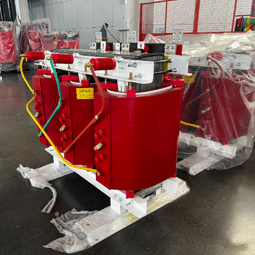
Lifting and Rigging Procedures
Always lift dry type transformers using the lifting lugs provided by the manufacturer. Do not lift by the enclosure or bushings. Use a spreader bar to prevent sling compression on the enclosure top. Maintain the transformer upright during lifting; tilting can shift the core-and-coil assembly.
For units above 1,000 kg, use a forklift with rated capacity or a mobile crane. Verify that the floor along the transport path can support the combined weight of the transformer and lifting equipment.
Seismic Mounting and Anchorage (Earthquake Zones)
In seismic zones, anchor the transformer to the foundation with bolts rated for 0.5g horizontal acceleration minimum. Use vibration-isolated anchors where required by code. The anchor pattern should match the transformer base plate holes. Torque all anchor bolts to the manufacturer’s specification.
Seismic restraints are required by code in many regions, including California, Japan, New Zealand, and parts of the Middle East. Failure to anchor transformers properly can result in catastrophic shifting during an earthquake, rupturing cable connections and creating fire hazards.
Vibration Isolation for Noise-Sensitive Locations
For installations in hospitals, offices, or residential buildings, install vibration isolation pads between the transformer base and the foundation. These elastomeric pads reduce structure-borne noise transmission. Isolation efficiency of 80-90% is achievable with properly selected pads. Do not use vibration isolation in seismic zones unless the isolators include seismic restraints.
Electrical Connections and Grounding
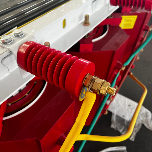
Primary and Secondary Cable Entry Methods
Dry type transformers typically use cable entry through the bottom or sides of the enclosure. Bottom entry is most common for clean installations where cables rise from below-grade trenches. Side entry is used when transformers are mounted against walls or when cable trays run at transformer height.
Use cable glands or conduit seals rated for the installation environment. Maintain proper bending radius for power cables to avoid insulation stress. Allow slack in cables near the transformer terminals to accommodate future maintenance movement.
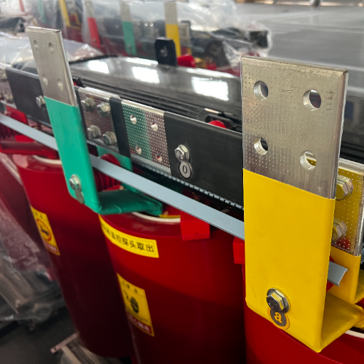
Busbar Connections and Torque Specifications
Transformer terminals are either bolted busbar connections or cable lug terminals. For bolted connections:
- Clean contact surfaces with electrical contact cleaner
- Apply thin layer of antioxidant compound for aluminum connections
- Use Belleville washers to maintain clamping force over thermal cycles
- Torque to manufacturer specifications using a calibrated torque wrench
- Mark torqued bolts with paint to indicate they have been set
Overtightening can deform busbars and crack cast resin terminals. Undertightening creates hot spots under load. Always follow the manufacturer’s torque chart.
Tap Changer Setting and Verification
Verify the tap changer position before energization. Off-load tap changers must be set with the transformer de-energized. Common tap positions are +/- 2 x 2.5% or +/- 5%. Select the tap that brings secondary voltage closest to nominal under actual primary voltage conditions.
After setting the tap, measure turns ratio with a TTR tester at all tap positions to confirm proper internal connections.
Grounding Requirements per IEC and NEC
Ground the transformer enclosure, core, and neutral point (if accessible) per local code. IEC 61936-1 requires protective bonding of all exposed conductive parts. NEC Article 250 requires equipment grounding conductors sized per Table 250.122.
Dry type transformers do not have tank grounding like oil immersed units, but the enclosure must still be bonded to the facility ground grid. Use copper conductors with green-yellow insulation for all protective earth connections.
CT and PT Installation for Metering and Protection
If current transformers (CTs) or potential transformers (PTs) are required for metering or protection, install them on the transformer bushings or in the cable compartments. CT polarity must be verified before connecting to relays. Incorrect CT polarity causes differential protection to misoperate.
Ventilation and Thermal Management
Heat Output Calculation by Transformer Losses
Transformer heat output equals total losses at rated load. Losses consist of no-load loss (core loss) plus load loss (winding loss). For a modern 1,000 kVA dry type transformer:
- No-load loss: approximately 1,500 W
- Load loss at 100%: approximately 10,000 W
- Total heat output at full load: approximately 11,500 W
For a 2,000 kVA unit, total losses may reach 20,000-25,000 W. The electrical room ventilation system must remove this heat continuously.
A data center contractor in Frankfurt installed a 2,500 kVA dry type transformer with the required 1,000 mm front clearance but only 300 mm rear clearance against a concrete wall. During summer peak loading, the restricted airflow caused a 15 K temperature rise above design. Thermal paper labels on secondary cables discolored after 8 months. Relocating the transformer 600 mm from the wall required a 3-day shutdown and $12,000 in rigging and electrical rework. The original installation saved 300 mm of room width but cost 40x that in remediation.
Natural Ventilation Design (Air Inlet/Outlet Sizing)
Natural ventilation uses the stack effect: cool air enters low, absorbs heat from the transformer, and exits high. The required free area for air inlet and outlet openings is calculated by:
Free area (m2) = Heat output (W) / (20 x delta T x v)
Where delta T is the allowable temperature rise above ambient (typically 10-15 K) and v is the air velocity through the opening (typically 1-2 m/s).
For a simpler rule of thumb: provide 1 m2 of free ventilation area per 1,000 W of heat loss. A 1,000 kVA transformer producing 11,500 W requires approximately 11.5 m2 of combined inlet and outlet free area. Divide this between inlet (low) and outlet (high) openings.
Forced Ventilation Requirements for Large Units
For transformers above 2,000 kVA or installations in hot climates, natural ventilation may be insufficient. Forced ventilation with exhaust fans maintains controlled airflow. Fan capacity is calculated by:
Airflow (m3/h) = Heat output (W) x 3.6 / (air density x specific heat x delta T)
For standard air at 1.2 kg/m3 and 1,005 J/kg.K, this simplifies to:
Airflow (m3/h) = Heat output (W) x 3.0 / delta T
For a 2,000 kVA transformer with 20,000 W losses and 15 K delta T:
Airflow = 20,000 x 3.0 / 15 = 4,000 m3/h
Worked Example: Ventilation Calculation for 1,600 kVA Room
A 1,600 kVA dry type transformer has total losses of approximately 16,000 W. The room is in a temperate climate with design ambient of 35 C and maximum allowable room temperature of 50 C (15 K delta T).
Natural ventilation free area required:
- Free area = 16,000 / (20 x 15 x 1.5) = 35.5 m2 total
- Inlet area (low): 17.8 m2
- Outlet area (high): 17.8 m2
If the room cannot provide this free area, add exhaust fans sized for 3,200 m3/h.
Temperature Monitoring and Alarm Integration
Install temperature monitoring on all dry type transformers. Common monitoring points include:
- Winding temperature (via fiber optic or resistance sensors)
- Core temperature
- Room ambient temperature
Set alarm thresholds at 90% of insulation class limit. For class F (155 C), alarm at 140 C winding temperature. Trip at 150 C. Connect alarms to the building management system or SCADA for remote monitoring.
Pre-Energization Testing and Commissioning
Insulation Resistance Testing (Megger)
Measure insulation resistance between each winding and ground, and between windings. Use a 1,000 V megger for low voltage windings and a 2,500 V megger for medium voltage windings.
Minimum acceptable values:
- New transformer: 1,000 M ohms or higher at 20 C
- In service: 100 M ohms or higher
Temperature correction: IR halves for every 10 C increase above 20 C. A reading of 500 M ohms at 40 C is equivalent to 2,000 M ohms at 20 C.
A commercial building in Manila hired an inexperienced contractor to install two 1,000 kVA VPI transformers. The contractor skipped insulation resistance testing because “new transformers don’t need it.” After energization, one unit developed a phase-to-ground fault within 72 hours. Investigation revealed moisture ingress during storage; the transformer had been stored outdoors under a tarp for 6 weeks before installation. The damaged unit required a complete rewind at 9,500.A9,500.A50 megger test would have caught the moisture-degraded insulation before energization.
Winding Resistance Measurement
Measure winding resistance for all phases at the same tap position. Compare values to factory test reports. Phase-to-phase resistance should balance within 2%. Significant deviation indicates loose connections, broken strands, or internal damage.
Turns Ratio and Vector Group Verification
Use a TTR (transformer turns ratio) tester to verify ratio at all tap positions. The measured ratio should match the nameplate within 0.5%. Vector group verification confirms the phase displacement between primary and secondary windings. Dyn11 means the secondary voltage lags the primary by 30 degrees. Yyn0 means zero phase shift.
An industrial plant in Mexico City commissioned a 1,600 kVA dry type transformer but did not verify the vector group. The contractor assumed Dyn11 based on the specification, but the unit was shipped as Yyn0 to match an existing installation. The phase displacement mismatch caused circulating currents in the parallel bus, tripping differential protection three times before an engineer identified the error. Vector group verification with a TTR tester takes 15 minutes and prevents days of troubleshooting.
Partial Discharge Measurement
Partial discharge testing verifies insulation integrity. Measure PD at 1.5x rated voltage per IEC 60270. For dry type transformers, acceptable limits are:
- Cast resin: less than 10 pC
- VPI: less than 50 pC
Values above these thresholds indicate voids, moisture, or contamination in the insulation system.
Protection Relay Settings and Functional Tests
Set overcurrent, differential, and thermal protection relays per the coordination study. Perform primary injection testing on CT circuits to verify relay pickup and timing. Test trip circuits to confirm breaker operation. Document all settings in the commissioning report.
Load Testing and Thermal Verification
After energization, monitor transformer temperature during the first 24 hours of loaded operation. Verify that winding temperature stabilizes below the alarm setpoint. Infrared thermography of terminals and busbars identifies loose connections before they cause failures.
Documentation and Handover Requirements
Complete commissioning documentation includes:
- Pre-installation inspection report
- Factory test reports
- As-built drawings showing final installation layout
- Pre-energization test results (IR, ratio, resistance, PD)
- Protection relay settings and test reports
- Thermal imaging report
- Commissioning certificate signed by responsible engineer
Ready to install your transformer? Send your voltage, kVA, and room dimensions for installation guidance and clearance verification.
Common Installation Mistakes and How to Avoid Them
Mistake 1: Insufficient Clearances
Installing transformers with less than code-required clearances restricts cooling airflow and prevents safe maintenance access. Always design to IEC 61936-1 or NEC Article 450 minimums, whichever is more stringent for your jurisdiction.
Mistake 2: Inadequate Ventilation
Undersized ventilation openings cause chronic overheating. Transformer life is reduced by approximately 5% for every 1 C above design ambient. Calculate ventilation requirements based on actual transformer losses, not rules of thumb.
Mistake 3: Improper Lifting and Handling
Lifting by enclosure edges instead of lifting lugs, tilting during transport, or dropping during placement can shift the core-and-coil assembly. Internal displacement causes noise, vibration, and insulation damage that may not appear for months.
Mistake 4: Skipped Pre-Energization Tests
The 50meggertestand15−minuteTTRverificationprevent50meggertestand15−minuteTTRverificationprevent10,000+ failures. Never energize without confirming insulation integrity and vector group. The cost of testing is negligible compared to the cost of troubleshooting an energized fault.
Mistake 5: Incorrect Grounding
Failing to bond the enclosure to protective earth creates shock hazards. Using undersized grounding conductors violates NEC and IEC requirements. Use green-yellow insulated copper conductors sized per local code tables.
Mistake 6: Ignoring Seismic Requirements
In earthquake-prone regions, unanchored transformers become projectile hazards. Seismic anchors are not optional where code requires them. The anchor system must resist 0.5g horizontal acceleration minimum.
Installation Cost Breakdown
Total Installed Cost Examples
Installation costs vary by region, but typical ranges excluding the transformer itself are:
| Component | 500 kVA | 1,000 kVA | 2,000 kVA |
|---|---|---|---|
| Foundation/concrete pad | $800-1,200 | $1,000-1,500 | $1,500-2,500 |
| Rigging and placement | $1,000-1,500 | $1,500-2,500 | $3,000-5,000 |
| Electrical connections | $1,500-2,000 | $2,000-3,000 | $3,500-5,000 |
| Ventilation (fans/ducts) | $500-1,000 | $1,000-2,000 | $2,000-3,500 |
| Testing and commissioning | $800-1,200 | $1,000-1,500 | $1,500-2,500 |
| Permits and inspections | $300-500 | $500-800 | $800-1,200 |
| Total installed cost | $5,000-8,000 | $7,000-12,000 | $12,000-20,000 |
Labor rates in North America and Western Europe run higher than in Asia, Africa, and Latin America. Add 30-50% for seismic anchoring, noise attenuation, or specialized enclosures.
Safety Requirements During Installation
Lockout/Tagout Procedures
Before working on any transformer installation, implement lockout/tagout on all energy sources: primary supply, secondary loads, and auxiliary circuits (fans, heaters, controls). Only qualified electricians should remove locks after verifying zero energy state.
Personal Protective Equipment
Installation personnel require:
- Hard hats
- Safety glasses
- Insulated gloves rated for system voltage
- Steel-toed boots
- High-visibility vests
- Arc flash protection for medium voltage work
Live Work Considerations
Avoid live work during transformer installation. De-energize both primary and secondary sides before making connections. If live work is unavoidable, follow NFPA 70E or local arc flash safety standards with appropriate PPE and work permits.
Post-Installation and Handover
As-Built Documentation Requirements
Update all drawings to reflect the actual installed configuration: transformer location, cable routing, grounding connections, and ventilation layout. As-built documentation is essential for future maintenance, troubleshooting, and insurance claims.
Warranty Registration and Conditions
Register the transformer warranty with the manufacturer within the required timeframe, typically 30 days of energization. Warranty conditions usually require:
- Installation by qualified personnel
- Compliance with manufacturer installation instructions
- Pre-energization testing documentation
- Loading within rated capacity
- Annual maintenance records
Training for Operations Staff
Train facility operators on transformer monitoring: how to read temperature displays, what alarm levels mean, and who to contact for abnormal conditions. Provide a one-page emergency procedure sheet posted at the electrical room entrance.
Scheduling First Maintenance Interval
Schedule the first maintenance inspection at 6 months after energization. This early inspection catches installation-related issues before they develop into failures. Subsequent intervals are typically annual. See our complete dry type transformer guide for maintenance planning.
Frequently Asked Questions
How Much Clearance Does a Dry Type Transformer Need?
Minimum front clearance is 1,000 mm for units up to 1,000 kVA and 1,200 mm for larger units. Side and rear clearance is 600 mm minimum for natural ventilation and 800 mm for forced-air cooled units. Top clearance to ceiling is 1,000 mm minimum.
Can You Install a Dry Type Transformer Outdoors?
Standard dry type transformers are designed for indoor installation. For outdoor use, specify a weatherproof enclosure with appropriate IP rating (IP54 or higher) or choose an oil immersed transformer designed for outdoor exposure.
What Foundation Is Required for a Dry Type Transformer?
A reinforced concrete pad 150-300 mm thick extending 100 mm beyond the transformer footprint on all sides. The foundation must support 2-4x the transformer weight and be level within 2 mm per meter. Steel frames are acceptable where floor loading is limited.
How Do You Calculate Ventilation for a Transformer Room?
Calculate transformer heat output from no-load plus load losses. Size natural ventilation openings using free area of 1 m2 per 1,000 W of heat loss, divided between low inlet and high outlet openings. For forced ventilation, size fans for airflow (m3/h) = heat output (W) x 3.0 / delta T.
What Tests Are Required Before Energizing a Dry Type Transformer?
Minimum pre-energization tests: insulation resistance (megger), winding resistance, turns ratio (TTR), and vector group verification. For critical installations, add partial discharge measurement and protection relay functional testing.
How Long Does Dry Type Transformer Installation Take?
A typical installation takes 1-3 days: Day 1 for foundation verification, rigging, and placement; Day 2 for electrical connections and grounding; Day 3 for testing and commissioning. Large or complex installations may require 5 days.
Can You Parallel Dry Type Transformers?
Yes, if both transformers have the same voltage ratio, vector group, and impedance (within 10%). Verify phase rotation and voltage matching before closing the paralleling breaker. Install circulating current protection for paralleled units.
What Is the Installation Cost for a 1,000 kVA Dry Type Transformer?
Total installed cost excluding the transformer itself ranges from 7,000to7,000to12,000 for a 1,000 kVA unit. This includes foundation, rigging, electrical work, ventilation, testing, and permits. Costs vary by region and complexity.
Conclusion
Dry type transformer installation demands attention to clearances, ventilation, electrical connections, and testing. The most expensive installation mistakes are also the most preventable: insufficient clearance, inadequate ventilation, and skipped pre-energization tests.
Follow the clearance tables in this guide for your transformer rating. Calculate ventilation based on actual heat output from transformer losses. Never energize without confirming insulation resistance, turns ratio, and vector group. These three tests take less than one hour combined and prevent the majority of installation-related failures.
For projects requiring cast resin or VPI transformers, review our cast resin transformer guide and VPI transformer guide for sub-type specific installation considerations.
Shandong Electric Co., Ltd. provides dry type transformers from 100 kVA to 5,000 kVA with complete factory testing and installation documentation. Send your room dimensions, transformer rating, and project location for clearance verification and installation guidance.