Dry Type Transformer for Data Center: Specs, Sizing & Selection Guide (2026)
Data centers lose an average of $9,000 per minute during unplanned outages. Yet many facility teams treat the transformer as a commodity component, assuming any dry type unit will suffice. In reality, selecting the wrong dry type transformer for a data center can create harmonic overheating, violate noise requirements in white space adjacencies, or cost hundreds of thousands in excess energy losses over the facility life.
This guide covers the complete process of specifying dry type transformers for data center applications. You will learn how to size transformers for IT and infrastructure loads, when to specify K-rated windings for UPS harmonics, what noise limits apply near server halls, how to configure N+1 redundancy for tier-rated facilities, and which dry type sub-type belongs in each data center zone.
Key Takeaways
- Data centers use dry type transformers because they eliminate oil spill risk, meet indoor fire codes, and require minimal maintenance.
- Cast resin transformers belong in mission-critical white space; VPI units suit electrical rooms and support spaces; open ventilated designs work only in non-critical auxiliary areas.
- Transformer sizing must include IT load, infrastructure load, diversity factor, and 20-30% growth margin before selecting kVA rating.
- K-rated transformers (K-13 or K-20) are essential when UPS systems and nonlinear loads create harmonic currents above 35% THD.
- Noise targets for white space adjacency typically require NC-45 to NC-55, often demanding low-loss core designs or acoustic enclosures.
- N+1 redundancy requires dual transformer configurations with automatic transfer for Tier III and Tier IV facilities.
For a broader overview of all dry type technologies, see our complete dry type transformer guide.
Why Data Centers Use Dry Type Transformers
Fire Safety and Indoor Code Compliance
Dry type transformers use air or solid resin insulation instead of liquid oil. This eliminates the combustible liquid hazard that fire codes restrict inside buildings. NFPA 75 (Standard for the Protection of Information Technology Equipment) and NFPA 76 (Standard for the Fire Protection of Telecommunications Facilities) both favor non-liquid insulated equipment in indoor electrical spaces.
Self-extinguishing cast resin and VPI transformers achieve fire behavior class F1 under IEC 60076-11. In the event of an external fire, the resin does not propagate flames. This property is essential when transformers sit inside the same building as millions of dollars of server equipment.
No Oil Spill Risk Near Critical Equipment
Oil immersed transformers carry the risk of tank rupture or seal failure, which can release insulating oil into the building. Even a small leak creates environmental cleanup liability and fire hazard. Dry type transformers eliminate this risk entirely. For data center operators who manage facilities in dense urban locations or lease space in multi-tenant buildings, this risk elimination can be a deciding factor.
Lower Maintenance Requirements
Transformers of this type are not obliged to undertake annual oil sampling to check the dissolved gas content or carry out filtration. This requirement is limited to visual inspection, confirmation of connection torques, and insulation resistance tests, periodically. With lean operations teams, it implies lower ongoing maintenance cost and very few opportunities for human error.
Environmental and Sustainability Considerations
Modern data centers face increasing pressure to reduce environmental impact. Dry type transformers contain no oil, require no oil disposal at end of life, and can be manufactured with lower-loss core steel that reduces energy consumption. Some operators now specify transformer efficiency as part of their green building certification strategy, knowing that transformer losses directly affect facility PUE (Power Usage Effectiveness).
Dry Type Sub-Type Selection for Data Center Zones
Not all dry type transformers belong in every part of a data center. Choosing the right sub-type for each zone balances protection level, cost, and repairability.
White Space / Mission-Critical Areas: Cast Resin
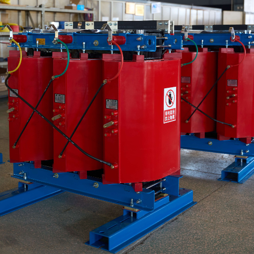
Mission-critical white space houses active servers, storage, and network gear. Transformer failure here threatens uptime directly. Cast resin transformers offer the lowest partial discharge (below 10 pC), highest moisture resistance, and greatest mechanical rigidity. Their fully encapsulated windings withstand the environmental stress of continuous duty and provide maximum reliability.
For Tier III and Tier IV facilities, cast resin is the standard specification for transformers feeding UPS systems and PDU distribution. The premium cost is justified by the cost of downtime. See our deep dive on cast resin transformer specifications for technical details.
Electrical Rooms and UPS Areas: Cast Resin or VPI
Electrical rooms adjacent to white space benefit from cast resin where budget allows, but VPI transformers are acceptable for standard commercial data centers with controlled indoor environments. VPI units offer solid resin insulation, good moisture protection, and repairability at 25-40% lower cost than cast resin.
The decision between cast resin and VPI in electrical rooms comes down to reliability tier and budget. If the facility operates at Tier II or below, and the electrical room has climate control, VPI is usually sufficient. For Tier III and above, cast resin remains the conservative choice.
Support Spaces: VPI or Open Ventilated
Chiller plants, UPS battery rooms, administrative offices, and loading docks do not require the same protection level as white space. VPI transformers deliver adequate moisture and dust protection for these areas at lower cost. Open ventilated dry type transformers can be considered only in clean, temperature-controlled auxiliary spaces where first cost is the dominant concern and repair access is easy.
Loading Docks / Exterior: Oil Immersed
Outdoor transformer installations, including pad-mounted units at the utility boundary, are outside the scope of dry type selection. These locations require oil immersed or cast resin outdoor-rated units. For more on outdoor options, see our dry type vs oil filled transformer comparison.
Zone-Based Selection Decision Matrix
| Data Center Zone | Recommended Type | Rationale |
|---|---|---|
| White space (server hall) | Cast resin | Maximum reliability, lowest PD |
| Electrical room (Tier III/IV) | Cast resin | Mission-critical adjacency |
| Electrical room (Tier I/II) | VPI | Cost-effective, adequate protection |
| UPS/battery room | Cast resin or VPI | Depends on tier and budget |
| Chiller plant | VPI | Support space, controlled indoor |
| Admin/office | VPI or open ventilated | Non-critical, cost priority |
| Loading dock exterior | Oil immersed | Weather exposure required |
A colocation facility in São Paulo was designing a new 6 MW data hall. The MEP consultant specified cast resin transformers for every indoor location, including chiller plant electrical rooms and administrative wing distribution. After reviewing the zone-based approach, the operator proposed cast resin only for white space and UPS feed transformers, switching chiller and office transformers to VPI units. The change saved $65,000 upfront without compromising Tier III compliance. Two years after energization, all units continue operating within design temperature limits.
If you need a more detailed methodology covering demand factors, harmonic calculations, growth margins, and real-world sizing scenarios, read Dry Type Transformer Sizing: Complete Methodology & Examples (2026).
Data Center Transformer Sizing Methodology
Calculating Total IT Load
Start with the total power consumption of all IT equipment in the target data hall. This includes servers, storage arrays, network switches, and any other active gear. Use nameplate ratings as a starting point, but recognize that actual consumption is typically 60-80% of nameplate. For planning purposes, sum the nameplate ratings and apply a realistic utilization factor.
Example: A data hall contains 500 kW of server nameplate, 150 kW of storage, and 50 kW of network gear. Total IT nameplate is 700 kW. At 70% average utilization, actual IT load is approximately 490 kW.
Adding Infrastructure Load
Add power consumed by supporting infrastructure. This includes:
- UPS system losses (typically 3-7% of throughput)
- Cooling and chiller loads (often 0.3-0.6 kW per kW of IT load)
- Lighting, security, and fire suppression
- PDU and switchgear losses
Continuing the example: UPS losses at 5% add 24.5 kW. Cooling at 0.5 ratio adds 245 kW. Lighting and misc add 15 kW. Total infrastructure is approximately 285 kW. Combined with IT load, total facility load is 775 kW.
Applying Diversity Factor
Not all equipment runs at peak simultaneously. Apply a diversity factor of 0.6-0.8 to account for partial loading, equipment rotation, and non-coincident peaks. For mission-critical facilities, use the conservative end (0.7-0.8). For commercial colocation with variable tenant loads, 0.6-0.7 may be appropriate.
Example at 0.75 diversity: 775 kW x 0.75 = 581 kW design load.
Future Growth Margin
Data center loads grow. Apply a 20-30% growth margin to avoid premature transformer replacement. This margin also accommodates temporary overloads and equipment refresh cycles.
Example with 25% margin: 581 kW x 1.25 = 726 kW total required capacity.
At 0.4 kV secondary, 726 kW translates to approximately 1,050 kVA. Standard transformer sizes are 1,000 kVA or 1,250 kVA. In this case, specify 1,250 kVA to ensure adequate headroom.
Worked Example: Sizing for 2 MW Data Hall
| Step | Calculation | Result |
|---|---|---|
| IT nameplate | 1,500 kW servers + 400 kW storage + 100 kW network | 2,000 kW |
| IT utilization (70%) | 2,000 x 0.70 | 1,400 kW |
| UPS losses (5%) | 1,400 x 0.05 | 70 kW |
| Cooling (0.5 ratio) | 1,400 x 0.50 | 700 kW |
| Lighting and misc | — | 50 kW |
| Total facility load | 1,400 + 70 + 700 + 50 | 2,220 kW |
| Diversity factor (0.75) | 2,220 x 0.75 | 1,665 kW |
| Growth margin (25%) | 1,665 x 1.25 | 2,081 kW |
| kVA at 0.4 kV | 2,081 / 0.4 / sqrt(3) | ~3,000 kVA |
For a 2 MW data hall, specify a 3,000 kVA transformer or dual 2,000 kVA units for N+1 redundancy.
K-Rated Transformers for Data Center Harmonics
What Is K-Rating and Why It Matters
K-factor is a rating that indicates a transformer’s ability to handle harmonic currents without excessive heating. Standard transformers are designed for sinusoidal loads. Data center loads are anything but sinusoidal. UPS systems, variable frequency drives, and switching power supplies generate harmonic currents that flow back through the transformer, causing additional heating in windings and core.
Without K-rating, a transformer serving harmonic-rich loads can overheat even when the measured RMS current is below its nameplate rating. The extra heat comes from the higher-frequency harmonic currents, which create additional I2R losses and eddy current losses that standard transformers are not designed to dissipate.
UPS Input Harmonics and Nonlinear Load Impact
The UPS system sits at number one on the list of generators of harmonics in the data center. In its operation, a rectifier in a step-up transformer will, by sudden switching off and on, draw current in pulses and not smooth sine waves; this builds up harmonic components at 3rd, 5th, 7th, 11th, and 13th orders. The total harmonic distortion (THD) at the input of the UPS system will jump to a level of 30-80%, depending on the rectifier technology.
Ordinary transformers, which bear heavily loaded through THDs, spiral to winding temperature-rise over the upper limits stipulated for the insulation class. It would not be surprising for a transformer rated to allow 100°C rising on a sinusoidal load to be jumping up toward 130–150°C with 50% THD, thus accelerating the pace of insulation decomposition and finally reducing its life span.
K-4, K-13, K-20: Which Rating for Your Load Profile
| K-Rating | Harmonic Content | Typical Application |
|---|---|---|
| K-4 | Up to 35% THD | Light commercial, linear loads |
| K-13 | 35-60% THD | Standard data center with UPS |
| K-20 | 60-80% THD | Heavy nonlinear loads, legacy UPS |
| K-30 | 80-100% THD | Extreme harmonic environments |
For modern data centers with transformerless or IGBT-based UPS systems, K-13 is usually adequate. Facilities with older 6-pulse rectifier UPS technology may require K-20. Always request a harmonic load study from the UPS manufacturer to determine actual THD at the transformer secondary.
K-Rated vs Harmonic Mitigating vs Active Filter
K-rated transformers are oversized and specially wound to dissipate harmonic heat. They do not eliminate harmonics; they simply survive them. Harmonic mitigating transformers use phase-shifting winding configurations to cancel certain harmonic orders. Active harmonic filters inject counter-phase currents to neutralize harmonics at the source.
For most data centers, K-rated transformers provide the most cost-effective solution. Where harmonic levels exceed K-20 capability, or where strict power quality standards apply, combine K-rated transformers with active filters for comprehensive harmonic management.
A data center in Singapore installed a standard 2,000 kVA transformer to serve a new UPS system. Within six months, thermal monitoring showed winding temperatures 25 degrees Celsius above the nameplate rise. Insulation resistance began declining. Investigation revealed the UPS 6-pulse rectifier produced 65% THD at the transformer secondary. The standard transformer was never designed for that harmonic content. Replacement with a K-13 unit resolved the overheating, and temperatures returned to within 5 degrees Celsius of design limits. The operator now mandates K-rating verification on every transformer specification.
Noise Requirements for Data Center White Space
Understanding NC and RC Noise Curves
Noise Criteria (NC) and Room Criteria (RC) are standard curves used to specify acceptable background noise levels in occupied spaces. Data center white space targets typically fall in the NC-45 to NC-55 range, depending on facility tier and operator preference. Administrative areas may require NC-35 or lower.
Transformer noise contributes to the overall mechanical and electrical background in a facility. A standard 2,000 kVA dry type transformer can generate 68-72 dB(A) sound power level, which translates to significant sound pressure in adjacent spaces if not properly managed.
Transformer Sound Power vs Sound Pressure
Sound power is the total acoustic energy emitted by the transformer. Sound pressure is what occupants actually hear at a given distance. Sound pressure decreases with distance and is affected by room acoustics, wall transmission, and vibration paths.
At 1 meter from a 70 dB(A) transformer, sound pressure is approximately 70 dB(A). At 3 meters, it drops to roughly 60 dB(A). In a reflective electrical room with hard surfaces, reverberation can increase perceived noise by 3-6 dB(A). Transformer rooms should include acoustic absorption on walls or ceiling to reduce reverberation.
Typical Noise Limits for White Space Adjacency
| Transformer Location | Target Sound Pressure at White Space | Typical Requirement |
|---|---|---|
| Adjacent electrical room (shared wall) | NC-45 | Low-noise core or enclosure |
| Electrical room 5+ meters away | NC-50 | Standard design may suffice |
| Below white space (floor separation) | NC-45 | Vibration isolation critical |
| Rooftop mechanical area | NC-55 | Distance often adequate |
Noise Mitigation Strategies
Specify transformers with low-loss core steel (Hi-B or domain-refined material) to reduce magnetostriction noise. Add anti-vibration pads between transformer base and floor structure. Specify acoustic enclosures or barriers for electrical rooms adjacent to white space. Consider cast resin transformers, whose solid epoxy mass provides natural damping compared to VPI or open ventilated designs.
N+1 Redundancy and Transformer Configuration
Tier Ratings and Transformer Requirements
The Uptime Institute Tier Standard defines four levels of data center reliability:
| Tier | Redundancy | Transformer Configuration |
|---|---|---|
| Tier I | None | Single transformer |
| Tier II | Partial | Single transformer with maintenance bypass |
| Tier III | Concurrently maintainable | Dual transformer N+1 |
| Tier IV | Fault tolerant | Dual transformer 2N or N+1 with diverse paths |
For Tier III and Tier IV facilities, N+1 redundancy at the transformer level means that the total installed capacity exceeds the peak load by one unit. If one transformer fails or is taken offline for maintenance, the remaining capacity can carry the full load.
Single Transformer vs Dual Transformer Configuration
Single-transformer configurations are simpler and less expensive but create a single point of failure. Dual-transformer configurations with automatic transfer switches provide redundancy but increase complexity and cost. For a 3,000 kVA load, dual 2,000 kVA transformers in an N+1 arrangement provide 4,000 kVA total capacity against a 3,000 kVA requirement.
Automatic Transfer Switch Integration
When a transformer fails or is removed for service, an automatic transfer switch (ATS) transfers the load to the alternate transformer within milliseconds. The ATS must be sized for the full load current and rated for the fault current available from both sources. Coordination between transformer impedance, breaker settings, and ATS transfer time is essential to avoid nuisance transfers or excessive voltage dips.
Maintenance Bypass Considerations
Even with N+1 redundancy, planned maintenance requires taking one transformer offline. Design the distribution system so that maintenance on one unit does not require de-energizing any critical loads. This typically means each transformer feeds separate switchgear bus sections with tie breakers that allow load transfer without interruption.
A hyperscale data center in Frankfurt operated dual 2,500 kVA transformers in an N+1 configuration. During a scheduled maintenance window, one transformer was de-energized for insulation testing and connection torque verification. The automatic transfer switched the full 2,200 kVA load to the alternate unit in under 100 milliseconds. Server racks experienced no power anomaly. The maintenance was completed in four hours, and the original transformer returned to service without any white space impact. The facility manager noted that the upfront cost of the dual-transformer configuration had paid for itself during the first maintenance cycle alone.
Efficiency Standards and PUE Impact
DOE 2016 and DOE 2027 Efficiency Requirements
The U.S. Department of Energy sets minimum efficiency standards for distribution transformers. DOE 2016 standards require three-phase dry type transformers to meet specified efficiency levels at 35% and 50% of rated load. A 1,000 kVA transformer must achieve at least 98.35% efficiency at 50% load under DOE 2016.
DOE 2027 standards, effective January 1, 2027, tighten these requirements by approximately 0.5-1.0% depending on kVA rating. Transformers manufactured after that date must meet the new minimums. For data center projects with 2027 energization dates, specifying DOE 2027-compliant units avoids early obsolescence.
EU Eco Design for Data Center Export Projects
Data centers in Europe or serving European customers must comply with EU Eco Design Directive requirements for transformer losses. Tier 1 (loss limits) and Tier 2 (premium efficiency) categories define maximum no-load and load losses. For data center export projects, verify that specified transformers meet the relevant Eco Design tier.
How Transformer Losses Affect Data Center PUE
PUE is calculated as total facility power divided by IT equipment power. Transformer losses add to the numerator. Consider a 3,000 kVA transformer serving 2,000 kW of IT load:
- At 98.5% efficiency: losses = 30 kW
- At 99.0% efficiency: losses = 20 kW
The 0.5% efficiency improvement saves 10 kW continuously. Over 8,760 hours per year at 0.10/kWh,thatis0.10/kWh,thatis8,760 annual savings per transformer. In a facility with four transformers, premium efficiency saves over $35,000 per year in direct energy cost alone.
Data Center Dry Type Transformer Specifications
Standard Voltage Configurations
Data center transformers commonly use these voltage configurations:
- Primary: 11 kV, 13.8 kV, or 33 kV from utility substation
- Secondary: 400/230 V three-phase four-wire for international projects, or 480/277 V for North American facilities
- Custom voltages available for non-standard utility supplies
Common kVA Ratings
| Data Center Size | Typical Total Load | Common Transformer Size |
|---|---|---|
| Small edge / POP | 200-500 kW | 500-750 kVA |
| Medium colocation | 1-3 MW | 1,500-3,000 kVA |
| Large hyperscale | 5-20 MW | 5,000-15,000 kVA (multiple units) |
Standard commercially available ratings for data center dry type transformers include 1,000 kVA, 1,500 kVA, 2,000 kVA, 2,500 kVA, and 3,000 kVA.
Insulation Class and Temperature Rise
Class F insulation (155 degrees C maximum) with 100 K temperature rise is standard. Class H insulation (180 degrees C) with 125 K rise is available for high-ambient or overload-capable designs. Specify temperature rise based on electrical room ventilation capacity and ambient design temperature.
Vector Group Selection
Dyn11 is the most common vector group for data center distribution transformers. It provides a stable neutral for single-phase loading and limits third-harmonic circulation. Yyn0 may be specified where neutral loading is significant, though it offers less harmonic isolation.
IP Rating and Enclosure Requirements
Standard indoor installation uses IP20 or IP23 ventilated enclosures. For data center electrical rooms with dust risk or proximity to white space, specify IP31 or higher. Where washdown or unusual contamination exists, consult the manufacturer for custom enclosure ratings.
Partial Discharge Limits for Mission-Critical Service
Cast resin transformers for white space and UPS applications should achieve partial discharge below 10 pC at 1.5 times rated voltage. VPI transformers for electrical rooms should measure below 50 pC. Always request factory PD test reports and witness testing for critical units.
Fire Safety Codes and Compliance
NFPA 75 and NFPA 76 Requirements
NFPA 75 addresses fire protection for IT equipment. NFPA 76 addresses telecommunications facilities. Both standards restrict the use of liquid-insulated transformers inside the building envelope unless specific containment and fire suppression measures are provided. Dry type transformers with F1 fire behavior class naturally comply with these requirements.
IEC 60076-11 Fire Behavior Classes
IEC 60076-11 defines three fire behavior classes:
- F0: No fire behavior requirements
- F1: Self-extinguishing in the event of fire
- F2: Fire behavior not specified
Data center transformers must achieve class F1. Verify this classification with the manufacturer and request test certification.
Local Fire Marshal Approval Considerations
Some jurisdictions require fire marshal approval for indoor transformer installations above certain kVA ratings. Approval may require submission of transformer fire test reports, installation drawings showing clearances, and coordination with the facility fire suppression system. Plan for this approval process in project schedules.
Placement and Clearance Requirements
Minimum clearances vary by local electrical code, but typical requirements include:
- 1 meter minimum from transformer enclosure to walls (for ventilation and access)
- 1.5 meters front clearance for breaker and bus access
- 2.5 meters minimum ceiling height above transformer top
- Non-combustible floor or containment pad beneath unit
Data Center Transformer Procurement Checklist
Use this checklist when specifying dry type transformers for data center projects:
- kVA rating — Sized for IT load + infrastructure + diversity + 25% growth margin
- K-rating — K-13 for standard UPS loads; K-20 for legacy 6-pulse rectifiers
- Dry type sub-type — Cast resin for white space; VPI for support spaces
- Noise level — Specify sound power limit based on white space adjacency (NC target)
- Insulation class — F (155 C) standard; H (180 C) for high ambient or overload
- Temperature rise — 100 K standard; verify against electrical room cooling capacity
- Efficiency standard — DOE 2016 or DOE 2027; EU Eco Design for European projects
- Partial discharge — Below 10 pC for cast resin; below 50 pC for VPI
- Fire behavior class — F1 required for indoor data center installation
- IP rating — IP20-23 for standard indoor; IP31+ for dusty or critical adjacencies
- Redundancy configuration — Single, N+1 dual, or 2N based on tier requirement
- Factory acceptance testing — Witnessed FAT including ratio, resistance, insulation, and PD
Installation Best Practices for Data Centers
Coordination with UPS and PDU Equipment
Transformer secondary voltage must match UPS input voltage requirements. Transformer impedance affects voltage regulation during UPS startup inrush and battery discharge cycles. Coordinate transformer impedance (typically 4-6%) with UPS manufacturer requirements to avoid excessive voltage dip.
Vibration Isolation and Seismic Requirements
Mount transformers on anti-vibration pads to prevent structure-borne noise transmission to white space. In seismic zones, provide seismic restraints per local code requirements. The transformer must remain anchored and operational after a design-level seismic event.
Thermal Management in Electrical Rooms
Electrical room ventilation must remove transformer heat loss plus heat from switchgear and UPS. Calculate total heat load and size HVAC accordingly. A 2,000 kVA transformer at 99% efficiency still dissipates 20 kW of heat continuously. Inadequate ventilation elevates ambient temperature and reduces transformer life.
Commissioning and Acceptance Testing
Before energizing, perform insulation resistance measurement, turns ratio verification, winding resistance testing, and vector group confirmation. For critical installations, witness factory acceptance testing and repeat key tests after delivery. Document baseline values for future maintenance comparison.
Frequently Asked Questions
Why Do Data Centers Use Dry Type Transformers?
Data centers use dry type transformers because they eliminate oil spill risk, meet indoor fire safety codes (NFPA 75/76), require minimal maintenance, and avoid environmental hazards associated with liquid-filled units. Dry type designs are the standard for indoor power distribution in mission-critical facilities.
What K-Rating Do I Need for My Data Center?
Most modern data centers with transformerless or IGBT-based UPS systems require K-13 rated transformers. Facilities with older 6-pulse rectifier UPS technology may need K-20. Request a harmonic load study from your UPS manufacturer to determine actual THD and select the appropriate K-rating.
Can I Use VPI Transformers in a Data Center?
Yes, VPI transformers are suitable for data center electrical rooms, support spaces, and non-critical distribution points. Cast resin transformers are preferred for mission-critical white space and UPS feeds. The choice depends on facility tier, budget, and environmental conditions.
What Noise Level Should I Specify?
For electrical rooms adjacent to white space, target sound pressure levels that meet NC-45 to NC-50 at the white space boundary. This typically requires low-loss core designs or acoustic enclosures. For rooftop or remote electrical rooms, NC-55 may be acceptable.
How Do I Size a Transformer for a Data Center?
Calculate total IT load plus infrastructure load (cooling, UPS losses, lighting). Apply a diversity factor of 0.6-0.8. Add a 20-30% growth margin. Convert the resulting kW to kVA using the secondary voltage. Round up to the next standard transformer size.
What Efficiency Standard Should I Specify?
For U.S. projects, specify DOE 2016 compliance as a minimum. For projects energizing in 2027 or later, specify DOE 2027 to avoid early obsolescence. For European projects, specify EU Eco Design Tier 1 or Tier 2 depending on efficiency goals and budget.
Do I Need N+1 Redundancy?
N+1 redundancy is required for Tier III and Tier IV facilities per Uptime Institute standards. Tier I and Tier II facilities may use single-transformer configurations. The decision depends on uptime requirements, budget, and the cost of downtime for the specific application.
Can Oil Filled Transformers Be Used in Data Centers?
Oil filled transformers are generally not permitted inside data center buildings due to fire code restrictions. They may be used for outdoor utility interface or pad-mounted installations at the site boundary. Inside the building envelope, dry type transformers are required.
Conclusion
Specifying a dry type transformer for a data center requires more than selecting a kVA rating. The right specification balances zone-based sub-type selection, harmonic load analysis, noise constraints, efficiency standards, and redundancy requirements. Getting any of these wrong creates operational risk, excess cost, or premature equipment failure.
The three decisions that matter most are sizing methodology that accounts for real load profiles and growth, K-rating that matches your UPS harmonic content, and sub-type selection that aligns transformer protection level with zone criticality. Noise and efficiency are secondary decisions that become important once the fundamentals are correct.
Use the procurement checklist in this guide to verify that your specification covers kVA, K-rating, sub-type, noise limit, efficiency standard, partial discharge, fire class, and redundancy before issuing purchase orders. Send your data center load profile, UPS specifications, and tier requirements to Shandong Electric Co., Ltd. for engineering review and a tailored transformer recommendation. Our team manufactures cast resin and VPI dry type transformers from 100 kVA to 5,000 kVA, built to IEC 60076-11 and customized for data center applications worldwide.