Three Phase Dry Type Transformers: Complete Engineering Guide for Industrial Power Distribution
Upon the growth of the CNC machining center from the manufacturing plant in Suzhou last year, an important discovery was made by its electrical contractor. Three-phase transformers suitable for supplying the motor load of the newly installed machines could not be replaced with the old single-phase transformers that were meant for the auxiliary power supply only. And acquiring properly sized three phase dry type transformers was going to take 16 weeks, which meant the ¥2 million production line expansion was in jeopardy. Such scenarios are commonplace across manufacturing industries, for the simple reason that, quite often, the basics of a single-phase versus a three-phase system are not grasped until it is too late.
Anyone with the responsibility of specifying power distribution equipment for industrial uses needs no further explanation that without three-phase power, modern manufacturing would not exist. But selecting a three phase dry type transformer is not just about voltage ratings. Phase configurations should be considered; also, precise kVA requirements should be resolved, and the applicable standards observed and met for the given purpose.
This guide shall provide the steps to take when specifying, sizing, and configuring Three Phase Dry Type Transformers for best results. We will discuss the technical basics of industrial installation and describe in numbers the real examples, and give selection requirements that you can use right away.
What Is a Three Phase Dry Type Transformer?
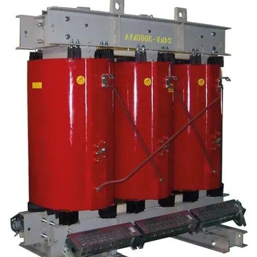
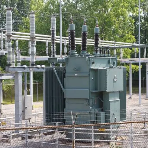
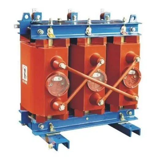
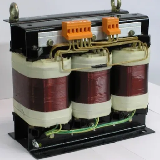
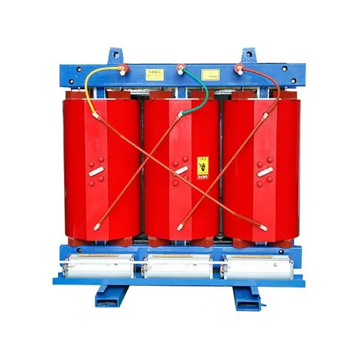
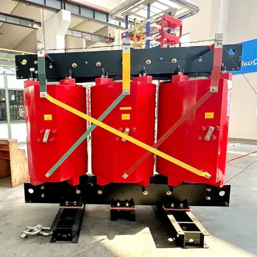
Three Phase Dry Type Transformers that use electromagnetic induction in terms of circuits supply power to alternators from circuits, a device functioning in relation to the handling of three-phase alternating current in the absence of liquid insulation. In contrast to the oil-immersed transformers, these ones apply air or solid, usually epoxy resin, or vacuum pressure impregnation, making them perfect for indoor use where fire risk and environmental protection are crucial.
How Three-Phase Transformers Work
Three-phase power speaks to three separate wave currents successively arriving at their highest peaks and distributed by 120 electrical degrees. In order that the power delivery is constant yet not merely pulsating as seen in single-phase systems, the magnetic field will then rotate. The core of the transformer has three legs (or a three-phase core assembly) with primary and secondary windings configured to compute the voltage change while keeping the mentioned relationship among them.
The biggest advantage? Three-phase systems supply 1.732 times more power than single-phase systems using the same conductor material. And that means significant savings in energy and costs for industrial plants with motors, pumps, or other sizeable pieces of equipment.
Key Components and Construction
Core Assembly: The grain-oriented silicon steel cores are three-phase, consisting of laminations to suppress the adverse effects of eddy current loss. The presence of a core, whether three-legged, four-legged, or five-legged, influences the serviceability of the transformer and the zero-sequence impedance.
Windings: Copper or Aluminum conductors encircle the core limbs, which in turn are covered with winding paper. Dry-type transformers have traditionally used sheet or foil wound constructions for better heat transfer and shape force resistance of the coil. It affects their short-circuit strength and impulse positions.
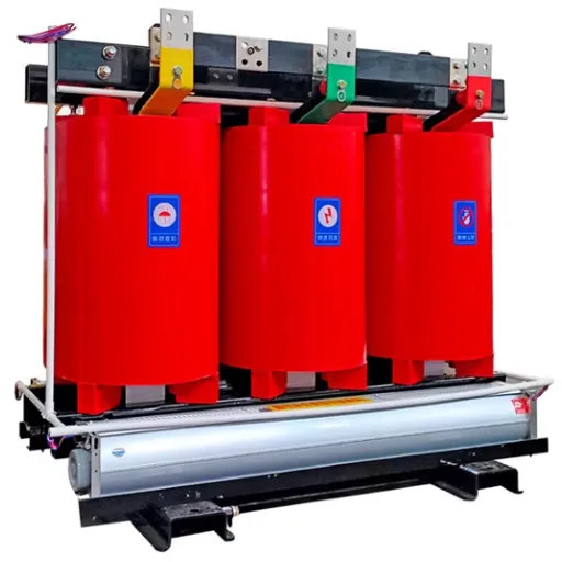
Insulation System: In cast resin transformers, the winding has been embedded and will be encapsulated with the epoxy resin in a vacuum. This means an internal direct canal, which can resist humidity as well as fire. Types of impregnation systems include the VPI, where winding coils are immersed in polyester resin for environmental use.
Enclosure and Cooling: steel enclosure with provision of venting for AN cooling or with a fan for AF cooling, forced air cooling. This safety is easy with an IP of up to IP00 due to the open style (meter). The rating might change for the dust and water impermeable type up to IP54, depending on the place of mounting.
Three Phase vs Single Phase: When to Choose Each
Understanding when three-phase power is essential—and when single-phase suffices—can save high costs while ensuring reliable operation.
Power Delivery Characteristics
Single-phase transformers produce a kind of power pulsation, where voltage crossing occurs twice in a single cycle. This gives torque pulsations in motors and necessitates larger conductors to transfer the same power. This type of issue does not arise with three-phase transformers; thus, a smoother power delivery can be achieved, and smaller, more efficient motor construction can result in this way.
| Characteristic | Single-Phase | Three-Phase |
|---|---|---|
| Power Delivery | Pulsating | Continuous |
| Conductor Efficiency | Lower | Higher (less copper for same kVA) |
| Motor Starting | Requires capacitors or special windings | Direct-on-line, smooth starting |
| Typical kVA Range | 10-167 kVA | 15-10,000+ kVA |
| Voltage Regulation | Poorer under load | Better, more stable |
Application Suitability Matrix
Choose Single-Phase When:
- Total load is under 50 kVA
- Powering lighting, small appliances, or office equipment
- Serving isolated rural or residential loads
- Budget constraints prevent the three-phase infrastructure
Choose Three Phase Dry Type Transformers When:
- Any three-phase motor over 5 HP is present
- Total load exceeds 50-75 kVA
- Running CNC machinery, pumps, compressors, or conveyors
- Data centers, manufacturing plants, or commercial buildings
- Future expansion is anticipated
In applying this process in dyeing in 2024, the engineering team of any Jiangsu-based textile mill thought they could save some money by making the change in single-phase power supply only. But the 75 HP new process pumps needed three-phase power. Savings through three-phase power require new transformer costs, but since they are now using smaller conductors and less energy is wasted, recovery is likely within 18 months.
Economic Considerations
It costs more to buy a three-phase transformer initially, but the delivered kVA cost is normally 15 to 30% lower than that of single-phase service if one includes the whole system cost (conductors, switchgear, labor for installation). This is the suggestion about most industrial applications: the three-phase total costs almost always win the analysis of total costs.
Three Phase Transformer Phase Configurations
Transformer windings are interconnected by the phase connection, generally leading to the voltage relationships, grounding characteristics, and harmonic behavior. Choosing which configuration is appropriate for your specific project is as important as determining the correct kVA rating.
Delta-Wye (Delta-Star) Configuration
Delta-Wye (IEC Dyn11) is considered the most common configuration of industrial distribution transformers. Connections are arranged as a delta (triangle) for the primary winding and a wye (star); Secondary are connected to the neutral side accessible.
Advantages:
- Possibility of earthing: So that a solid neutral can be made available from the wye secondary for single-phase loading and system earthing.
- Voltage transformation: The ratio of line-to-line voltage is equal to the number of turns multiplied by √3 (e.g., 11kV/400V).
- Harmonic suppression: The delta secondary suppresses the third harmonic current, preventing it from being allowed to flow up through the system.
- Phase displacement: The phase angle of the 30-degree shift, i.e., the natural isolation through Dyn11 in the middle of the primary and secondary fault currents.
Some typical applications are in an industrial plant distribution, commercial buildings, and data center electrical power.
Delta-Delta Configuration
Both primary and secondary windings are connected in a delta. This configuration maintains the voltage ratio without the √3-factor and provides no phase displacement.
Advantages:
- Simple voltage ratio (directly proportional to turns ratio)
- No phase shift between primary and secondary
- Can operate with one phase disabled (as open delta) at reduced capacity
Limitations:
- No neutral point on either side
- Third harmonics circulate in the windings
- More susceptible to voltage unbalance under unbalanced loads
Typical applications: Industrial motor loads, mining operations, and systems where phase displacement would cause synchronization issues.
Wye-Wye Configuration
Both sides are connected in a wye, providing neutral points on both primary and secondary.
When to Use:
- When both systems require grounded neutrals
- For very large transformers where winding insulation considerations favor wye connections
- In systems where phase displacement must be avoided
Caution: Wye-Wye transformers can experience ferroresonance and neutral instability under certain conditions. They typically require a tertiary delta winding to provide a path for third-harmonic currents.
Open Delta (V-V) Configuration
Using two transformers instead of three to provide three-phase power. This is typically an emergency or temporary arrangement.
Capacity Limitation: An open delta bank provides only 57.7% of the rated capacity of a full three-transformer delta-delta bank. The remaining capacity (86.6% of rated) is available as a safety margin, but sustained operation above 57.7% causes overheating.
Use Cases: Emergency restoration, temporary construction power, or when one transformer in a delta-delta bank fails and immediate replacement isn’t available.
Configuration Selection Flowchart
Start: What is your primary voltage source?
- Utility distribution (11kV, 20kV, 33kV) → Delta-Wye recommended
- Generator or isolated source → Consider grounding requirements
- Existing delta system → Match configuration or use an isolation transformer
Secondary requirements:
- Need 400/230V with neutral for mixed loads? → Delta-Wye
- Pure three-phase motor loads only? → Delta-Delta acceptable
- Synchronization with other systems? → Check phase displacement compatibility
How to Calculate Three Phase Transformer kVA
Accurate sizing is critical. Undersized transformers overheat, fail prematurely, and create safety hazards. Oversized units waste capital and may operate inefficiently at light loads.
Primary Calculation Formula
The fundamental formula for three-phase kVA calculation is:
kVA = (√3 × V_L × I_L) / 1000
kVA = (1.732 × Line Voltage × Line Current) / 1000
Where:
- V_L = Line-to-line voltage (Volts)
- I_L = Line current (Amperes)
- √3 ≈ 1.732
Reverse calculation (finding current from known kVA):
I_L = (kVA × 1000) / (√3 × V_L)From Power and Power Factor
When you know the power consumption in kilowatts:
kVA = kW / Power FactorTypical power factors by load type:
- Resistive loads (heaters, incandescent lighting): 0.95-1.0
- Mixed industrial loads: 0.80-0.90
- Motor-heavy loads with VFDs: 0.75-0.85
- Poor power factor (uncorrected): 0.60-0.70
Step-by-Step Industrial Sizing Example
Scenario: A new manufacturing facility in Shandong Province needs to size a transformer for their production line.
Step 1: List all connected loads
| Equipment | Power (kW) | Quantity | Total (kW) |
|---|---|---|---|
| CNC Machining Center | 45 | 3 | 135 |
| Hydraulic Press | 30 | 2 | 60 |
| Conveyor Systems | 15 | 4 | 60 |
| Cooling Pumps | 7.5 | 6 | 45 |
| Compressed Air | 22 | 1 | 22 |
| Lighting & Auxiliary | 25 | 1 | 25 |
| Total Connected Load | 347 kW |
Step 2: Apply the simultaneity (diversity) factor
Not all equipment runs simultaneously. For manufacturing, a simultaneity factor of 0.70-0.80 is typical:
Maximum Demand = 347 kW × 0.75 = 260.25 kWStep 3: Convert to kVA using power factor
Using a conservative power factor of 0.85:
kVA = 260.25 kW / 0.85 = 306 kVAStep 4: Add future expansion margin
Engineering best practice is a 20-30% margin for growth:
Required kVA = 306 kVA × 1.25 = 382.5 kVAStep 5: Select standard rating
Standard sizes closest to 382.5 kVA are 400 kVA or 500 kVA. Given the margin already applied, 400 kVA is the appropriate selection. However, if high motor inrush currents or significant future expansion are expected, 500 kVA provides additional headroom.
NEC and IEEE Sizing Guidelines
Intermittent loads: NEC Article 210.20(A) requires a transformer provisioned to power calculated loads where demand can last over 3 hours. In essence, it means:
- Calculated: 400 kVA
- Transformer Minimum: 400 kVA x 1.25 = 500 kVA
Maximum Loading Recommendation: According to IEEE C57.96, the continuous rating should not exceed 80 percent of the nameplate rating to achieve longevity and account for the unbalanced phases.
Motor Starting Considerations: Large motors, especially those that start direct-on-line, can draw as much as 6 to 8 times their full-load current at startup. In the case of large transformer supplies, the high starting inrush loads may make them oversized or may require the use of reduced-voltage starting methods.
Standard Three Phase kVA Ratings and Specifications
Understanding standard ratings helps you select from available options and ensures you’re specifying realistic requirements to manufacturers.
Common Industrial Ratings
Three-phase dry-type transformers are manufactured in standardized kVA ratings following the preferred number series (R10 or R20 series per IEC 60076). Common industrial ratings include:
| kVA Rating | 480V FLA | 400V FLA | 208V FLA | Typical Application |
|---|---|---|---|---|
| 150 | 180 | 216 | 416 | Small workshops, retail |
| 300 | 361 | 433 | 833 | Medium industrial |
| 500 | 601 | 722 | 1,388 | Large industrial |
| 750 | 902 | 1,083 | 2,082 | Heavy manufacturing |
| 1000 | 1,203 | 1,444 | 2,776 | Large facilities |
| 1500 | 1,805 | 2,165 | 4,164 | Substations |
| 2000 | 2,407 | 2,887 | 5,553 | Industrial plants |
| 2500 | 3,007 | 3,608 | 6,940 | Large substations |
FLA = Full Load Amperes
Voltage Levels and Taps
Primary Voltages (typical for dry-type distribution):
- 6.6 kV, 10 kV, 11 kV (Asian/African areas)
- 13.8 kV, 20 kV (Americas)
- 22 kV, 33 kV (voltage levels of utility distribution)
- 480V, 600V (voltage bands of industrial distribution)
Secondary Voltages:
- 400/230V (IEC standard; 50 Hz regions)
- 480/277V (industrial North American primary voltage system)
- 208/120V (commercial North American primary voltage system)
- 690V (for industrial motor loads)
Tap-changers: In many transformers, ± 2.5% and ±5% primary winding taps are included for compensation of minor variations in the source voltage. These are normally operated with no load, although some configurations have incorporated the use of on-load tap-changing (OLTC) as well for dynamic voltage regulation.
BIL (Basic Insulation Level) Ratings
BIL defines the transformer’s ability to withstand lightning and switching surge voltages:
| Max System Voltage | Standard BIL |
|---|---|
| 1.2 kV | 30 kV |
| 15 kV | 95 kV |
| 24 kV | 125 kV |
| 36 kV | 170 kV |
Higher BIL ratings are available for areas with high lightning activity or critical applications.
Key Selection Criteria for Three Phase Dry Transformers
Beyond kVA and voltage, several technical parameters significantly impact performance and suitability.
Capacity and Load Profile
Maximum Demand vs Average Load: Transformers should be sized for maximum demand, not average load. However, chronically light loading (below 30% of rating) results in poor power factor and reduced efficiency.
Load Profile Types:
- Continuous: Base industrial loads (pumps, HVAC) — size at 80% of rating max
- Intermittent: Cyclic manufacturing equipment — consider thermal time constants
- Emergency: Standby power — can use higher loading for short durations
Cooling Method Selection
AN (Air Natural): Utilizes natural convection, where it flows through ventilation openings. It is less noisy, normally below 55 dB, contains no parts that might produce sound, but has comparatively less capability to dissipate heat.
AF (Air Forced): This increases the amount of flow by adding simple cooling fans. Generally provides an addition in capacity (approximately 30-40%), may define smaller sizes for the housing. Complicates things by creating the need for maintenance and power to run the fan, but also makes the machine noisier (average noise 60-70 dB).
Selection Criteria:
- Indoor installations with adequate ventilation: Typically adequate for up to 1500-2000 kVA.
- Space-constrained installations: Smaller enclosure with AF
- High ambient temperatures (>40°C): AF compensates insulation derating.
- Noise-sensitive environments: If not fanless (i.e., with noise limitation), one must use little noise fans with airflow; AN is preferable.
Insulation Class and Temperature Rise
| Insulation Class | Max Continuous Temp | Standard Temp Rise | Hot-Spot Allowance |
|---|---|---|---|
| Class A | 105°C | 55°C | 10°C |
| Class E | 120°C | 70°C | 15°C |
| Class B | 130°C | 80°C | 15°C |
| Class F | 155°C | 100°C | 15°C |
| Class H | 180°C | 125°C | 15°C |
For a normally used temperature rise by transformers, a Class F insulation system is generally 100 degrees, marked by a short or long life and compact size. Class H, 180°C insulation suitable for very high temperatures, would be considered for the highest temperature feats or the smallest transformers.
Hot-Spot Consideration: That is, whenever the transformer is operating, it generates much heat in any of the parts making contact. The point at which failure occurs is known as the hot spot.
Impedance and Voltage Regulation
Impedance (%Z or %Z) affects:
- Voltage regulation: The greater the impedance, the greater the voltage drop under load.
- Short-circuit current: The greater the impedance, the lower the fault current.
- Parallel operation: Operational impedance shall be matched within 7.5% for proper load sharing.
Typical Impedance Values:
- Distribution Transformers (≤1000 kVA): 4-6%
- Power Transformers (>1000 kVA): 6-10%
- High Impedance Designs: 8-15% (for fault current limiting)
Voltage Regulation Formula:
Regulation (%) = (V_no_load - V_full_load) / V_full_load × 100The standard ratings of voltage control on dry-type transformers are 2-4% at full load, depending on impedance as well as power factor.
K-Factor Ratings for Non-Linear Loads
Modern industry facilities with variable frequency drives and uninterrupted power supplies, and, additionally, electronic ballasts will produce harmonics that intensify the tranny heating.
K-Factor Definition: A value of transformer efficiency in processing harmonic loads so that one would not exceed most temperature limits due to heat loss incurred by various factors. The K-factor of a harmonic system is equal to the square sum of every harmonic current multiplied by the square of their ordinal number.
| K-Factor | Application |
|---|---|
| K-1 | Linear loads only (motors, resistance heaters) |
| K-4 | Light non-linear loads (<25% of total) |
| K-13 | Moderate non-linear loads (25-50%), typical with VFDs |
| K-20 | Heavy non-linear loads (>50%), data centers, telecom |
Specifying K-Factor: When in doubt, specify K-13 for industrial applications with VFDs. The additional cost (typically 10-20% over standard) is recovered through extended transformer life.
Industrial Applications by Sector
Understanding how three phase dry type transformers are used throughout industries can help greatly in ascertaining the specifications required for the established practices.
Manufacturing and Industrial Plants
A significant piece of the infrastructure is a robust, reliable power distribution demanding clean, dependable energy. These are three phase dry type transformers that are useful as:
Motor Load Centers: Sources are motor control centers (MCC), as well as power surge feeders for production machinery. It delivers the three-phase power at 400/480V delta-wye from motors and has the 230/277V single-phase supply for use in control and lighting.
Process Power Distribution: It protects sensitive processing equipment from variations in utility voltage. Casually colored transformers are designed to be entirely dust and moisture-resistant for maintenance-free use in rough industrial environments.
Case Example: A Shanghai automotive parts manufacturer had already power unloaded 2000 kVA dry-type transformers in the stamping house. The enclosed cast-resin was powder-coated and stood the metal dust and vibration, while the K-13 rating fitted it against the VFD loads on the press feeders. After operating for two years, the maintenance team stated they had zero issues compared to the quarterly oil testing they did with their earlier oil-filled units.
Data Centers and Critical Facilities
Reliability, efficiency, and minimum fire hazard are what asks to dry-type transformers in a data center standard.
UPS System Integration: It steps down utility voltage (typically 11 or 20 kV) to the 400 or 480 volts that a UPS system needs. Tight coupling means compact, low-loss units.
Redundant Configurations: N+1 or 2N redundancy designs have at least the usage of numerous smaller transformers (for example, 4× 1000 kVA instead of 2× 2000 kVA) to ensure maintenance or equipment failure does not interrupt services.
Efficiency Priorities: The efficiency of a transformer is preferred since energy loss here heats the unit, which then needs to chill with an air-conditioning unit (double penalty, loss of energy as well as the cost of cooling). The premium-efficient units, which can no longer be bought by the time 2029 arrives due to DOE’s efficacy standard, are the norm.
Renewable Energy Integration
Solar farm and wind installations are often dependent on the provision of step-down transformers to link generation to the grids for distribution purposes.
Solar Farm Interconnection: The central inverters have an output of approximately 400-800V AC, which means it requires to be step-up till the medium voltage (10-35 kV) to be collected. Otherwise, Also, the string inverters could also be connected directly through pad-mounted or dry-type transformers at the array level.
Wind Turbine Transformers: At this juncture, each turbine has its own step-up transformer optimized (for offshore installations, often dry-type or compact to save space) for raising generator voltage to collect system levels.
Bidirectional Operation: Generally, grid-tied renewable systems are designed to have transformers in one or other of their directions of power flow. Distribution transformers are usually sufficient, but verification is now at the manufacturer’s to ascertain the occurrence on the customer site of severe power reversals.
Commercial and Infrastructure
High-Rise Buildings: Dry-type transformers as part of the electrical room are situated in between floors to avoid using bulky oil-filled transformers. Fire-safe construction does away with the requirement for oil containment or fire suppression systems.
Shopping Malls and Hospitals: Continuous operation requirements favor dry-type reliability. Hospitals often specify cast resin transformers with low partial discharge (<10 pC) for maximum reliability.
Metro and Railway Systems: Traction power supply uses specialized dry-type rectifier transformers, often with 12-pulse or 24-pulse configurations to minimize harmonic injection into the grid.
Standards and Certifications for Three-Phase Units
Compliance with recognized standards ensures safety, performance, and regulatory acceptance.
IEC 60076-11 Requirements
IEC 60076-11 is an initial international standard for dry-type transformers. The main features include:
Scope: Dry-type transformers (including auto transformers) with the highest voltage equipment up to 36/72.5 kV, rated power per unit of at least 5 kVA and 15 kVA for single and three-phase, respectively.
Environmental and Fire Behaviour Classes:
- E0, E1, E2: Environmental classes indicating the capability of undergoing condensation and pollution (higher E2).
- F0, F1: Fire behaviour classes (F1 else self-extinguishing, no flame propagation)
- C1, C2: Climatic classes of transportation, storage, and operation
Temperature Rise Limits:
- By the class of insulation (100°C for Class F and 125°C for Class H)
- The maximum limit of the hot-spot temperature during operation shall be that of the insulation class.
Testing Demand:
- Tests of the windings’ low endurance, a ratio of turns, an impedance of short-circuit, load, and interruption of the loss of load
- Temperature-rise tests, lightning impulse test, partial discharge test
- Special tests: Short-circuit withstand, sound level, enclosure IP verification
IEEE C57.12.01 Standards
In North America, there is a standard that governs dry-type distribution and power transformers. These transformers are rated in the following ranges:
- Distribution: Three-Phase, 15 – 500 kV A
- Power: Three-Phase, 501 kVA and Larger
Standard Configurations
- Delta-Wye: Perfect for distribution purposes since it provides neutral and phase shift.
- Delta-Delta: An allowed alternative for the appropriate applications.
- Wye-Wye: Generally avoided unless equipped with tertiary delta windings.
Temperature Rise:
- Standard: Rise by 80°C for a 220°C insulation system (most common).
- Optional: Lean back 115°C or 150°C increased temperature with an identical system of insulation (can load higher or design/build more compact).
Sound Level Limits:
NEMA ST-20 specifies a standard test for decibel levels plotted as a function of kVA rating. decibels-measured at 30 cm from the transformer surface (or 1 meter for larger units)
Testing Requirements
Routine Tests (performed on every unit):
- Measurement of Winding Resistance
- Measurement of Voltage Ratio and Phase Shift Verification
- Measurement of Impedance of Short-Circuit and Load Loss
- Measurement of No-Load Loss and Current
- Voltage tolerance test (dielectric test)
- Impulse voltage withstand test
Type Tests (Done on representative unit):
- Temperature rise test
- Lightning impulse test (BIL verification)
- Partial discharge measurement (for cast resin units)
Special Tests (if specified):
- Short circuit withstand test
- Sound level measurement
- Measurement of harmonics and no-load current
- Measurement of power taken by fans and pumps
Regional Certification Requirements
China (GB Standards):
- GB 1094.11: Dry-type power transformers
- GB/T 10228: Technical parameters and requirements
- CCC certification is a must for the local market
Europe:
- CE-mark is mandatory
- EcoDesign Directive on the efficiency of operation
- Local requirements like the German KTA 1401 for nuclear applications
North America:
- UL 1561 is listed (United States)
- CSA C22.2 No. 47 Certification (Canada)
- DOE efficiency regulations (10 C. F. R. 431).
Middle East/Africa:
- Often requires IEC plus local testing
- Some utilities require a specific witness testing protocol
Installation Best Practices
Proper installation ensures safety, performance, and longevity.
Site Preparation and Clearance
Minimum Clearances (per IEEE C57.12.59 and manufacturer specifications):
- Rear (opposite terminals): 100 mm – 150 mm for units up to 1000 kVA.
- Sides: at least 150 mm – 200 mm.
- Front (terminal access): 900 mm – 1 200 mm for maintenance
- Top: 300 mm – 500 mm – from the ceiling (even more for the AF cooled units)
Air ventilation requirements: Basically, the need for enough air from outside to pass through the room or enclosure in good natural convection. Calculating the required ventilation area is quite difficult.
Required Area (m²) = (Total Losses in Watts) / (7 × √Height of opening)
Height is supposed to be in meters, in which the constant 7 is for natural convection effectiveness.
Installing Base and Mount:
- Propping up to a minimum of 1500 kVA transformers typically requires beams in steel construction or floor stands.
- Large jack mounting typically entails using housekeeping pads and vibration isolation.
- Reboring of the unit in an environment facing seismic disturbance.
Connection Guidelines
Phase Rotation Verification: Before energization, one must check phase rotation (clockwise A-B-C) compatible with the system requirements. Reverse rotation results in the operation of motors in the reverse direction.
Grounding Requirements:
- The transformer neutral must be solidly grounded (for wye secondary)
- The Transformer enclosure must be bonded to the equipment grounding conductor
- Grounding electrode conductor sized per NEC Article 250
Conductor sizing: Size primary and secondary conductors utilizing NEC Article 310 (or local electrical code) for ampacity and voltage drop. Typical maximum voltage drop: 2% at full load.
Bushing and Terminal Connections:
- Use flexible connections that can accommodate vibration and thermal expansion
- Torque connections to manufacturer specifications.
- Apply an anti-oxidizing paste to the aluminum connections.
Parallel Operation Considerations
Three-phase transformers can be operated in parallel to share load, but strict requirements must be met:
Requirements for Paralleling:
- Same phase displacement (vector group)
- Same voltage ratio (within 0.5%)
- Same impedance (within 7.5%)
- Same kVA rating (preferred) or proper ratio for load sharing
- Same phase sequence (verified before connection)
Circulating Current Prevention: Any voltage difference between transformers creates a circulating current that causes heating without delivering useful power. The tighter the tolerances above, the lower the circulating current.
Maintenance and Troubleshooting
Dry-type transformers require less maintenance than oil-filled units, but proper care extends service life.
Routine Inspection Schedule
Monthly (Visual):
- Check for unusual noise or vibration
- Verify cooling fans are operating (AF units)
- Inspect for dust accumulation on cooling surfaces
- Check termination tightness indicators if fitted
Quarterly:
- Clean cooling air paths (compressed air, vacuum)
- Check and record operating temperatures
- Inspect for corrosion or damage to the enclosure
- Verify control and alarm functions
Annually:
- Measure insulation resistance (megger test)
- Check torque on all accessible connections
- Clean and inspect termination points
- Verify protection relay settings and operation
- Partial discharge measurement (for critical units)
Common Three-Phase Issues
A phase imbalance is said to be 2% plus or minus some difference in voltage or current between two or three phases and is another indication of likely problems.
- Causes: Unbalanced distribution of loads, poor connections or open circuits, negative changes in windings.
- Detection: Monitor using power quality analyzers
- Correction: Redistribute loads or subdivide single-phase loads, and correct the identified connection problem
Overheating: If the temperature exceeds what is indicated on the transformer nameplate value, then it decreases the life of the insulation Λ in the exponential Arrhenius equation
- Causes: Overloading, remaining current, bad ventilation, the lack of cooling passages or blocked cooling halls
- Detection: RTD or thermocouple monitoring or by using infrared thermography.
- Correction: Load reduction, better cooling, cleaning cooling corridors, and installation of K-rated transformers for harmonics.
Partial Discharge (Cast Resin Units): Internal voids or cracks in resin can cause partial discharge, which means eventual failure.
- Causes: Material defects, thermal cycling, mechanical stress
- Detection: PD measurement during maintenance or online monitoring.
- Correction: Change the equipment if the charge exceeds 50-100 pC levels, depending on age.
Insulation Degradation: The insulation resistance falls due to degradation by aging or moisture penetration.
- Measurement: Meg ohmic tests conducted between 500V and 1000V DC.
- Acceptable Values: >100 MΩ for new transformers, >10 MΩ for operational equipment
- Trending: Tracking the trend in values is necessary, where sudden slumps may refer to problems.
Conclusion
Specifying three phase dry type transformers requires attention to technical details that directly impact performance, safety, and total cost of ownership. The key takeaways for your next project:
- Size properly using kVA calculations with simultaneity factors, power factor correction, and future expansion margins
- Select appropriate phase configuration — Delta-Wye serves most industrial applications, but verify compatibility with your specific loads
- Consider environmental factors, including cooling method, insulation class, and IP ratings, for your installation environment
- Specify K-factor ratings when serving VFD loads or other non-linear equipment
- Verify standards compliance — IEC 60076-11, IEEE C57.12.01, or GB standards, depending on your market
Three phase dry transformers are extremely beneficial for industrial use due to their fire resistance feature, especially when used indoors, their almost zero maintenance, and the fact that they meet power quality requirements. When units of this type are correctly sited and put in the required locations, there are many years of trouble-free operation.
Need help specifying a three-phase transformer for your project? Shandong Electric Co., Ltd. provides custom transformer solutions with engineering support through design, manufacturing, and commissioning. Contact our engineering team to discuss your specific voltage, kVA, and configuration requirements.