

BESS Transformer Harmonics: What to Specify at the PCS Interface

Specify BESS transformer harmonics through three linked agreements: the PCS waveform data, the transformer’s thermal assessment, and the system’s harmonic acceptance criteria. A headline current-distortion percentage cannot replace that interface package.
For EPC engineers and procurement teams, the practical task is to make those agreements traceable. Which PCS configuration produced the data? Which operating conditions did the transformer designer assess? Where will the completed plant demonstrate compliance? Start with the overall BESS transformer selection and interfaces if the equipment arrangement is still being defined, then use the checklist below to close the harmonic interface.
Key takeaways
- Request the current spectrum with its current base, operating conditions and document revision.
- Obtain a transformer capability assessment against that agreed duty; avoid an assumed universal K-rating.
- Treat transformer heating tolerance and harmonic reduction as separate functions.
- Agree the grid assessment location, network assumptions and site verification plan independently of factory evidence.
Separate transformer heating from grid harmonic compliance
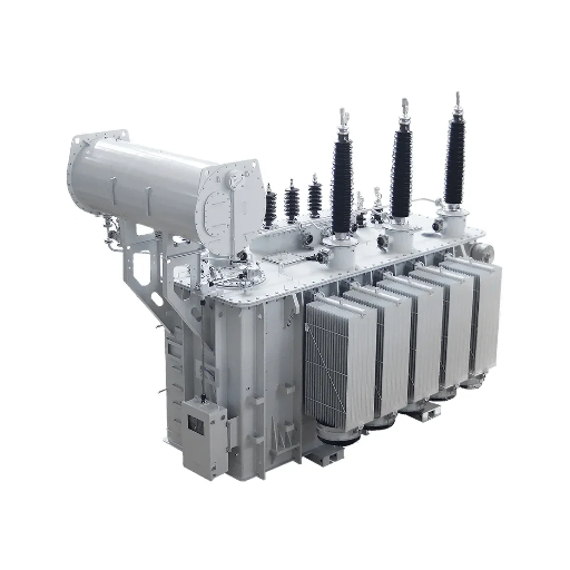
The transformer and the grid connection answer different engineering questions. A useful specification gives each question its own evidence and responsible reviewer.
What the transformer designer needs to assess
IEEE C57.110-2018 addresses transformer capability with nonsinusoidal load currents and the specification of new transformers for such duty. It provides a basis for asking how the proposed transformer will accommodate the supplied current waveform. It does not justify assigning every battery energy storage system the same harmonic rating.
Ask the designer to identify the waveform revision used, the assessment method, the operating envelope and the applicable equipment scope. Include ambient conditions, cooling assumptions and the intended duty in that response. A statement such as “suitable for inverter loads” leaves these inputs unclear.
Where the project verifies power quality
Mark the PCS AC terminals, transformer winding connections and point of common coupling (PCC) on the project single-line diagram. Label the location associated with every waveform report and acceptance criterion. A result measured at one location should not be presented as evidence for another without an agreed assessment.
IEEE 519-2022 addresses steady-state harmonic control at the PCC. Its system-level requirements do not constitute a transformer thermal capability certificate. The project engineer and network operator should confirm the applicable connection requirements, assessment boundary and limits for the actual jurisdiction.
Keep two distinct deliverables: a transformer design-basis response and a plant harmonic compliance assessment. Both should reference the same equipment arrangement and compatible operating assumptions.
Request a usable PCS harmonic data package
The power conversion system (PCS) supplier’s data should allow other parties to understand what was measured or modeled. Use the following table as a recommended engineering handoff, adapting it to the project rather than treating every row as a universal statutory requirement.
| Information to request | Conditions or reference to identify | Evidence owner | Downstream use |
|---|---|---|---|
| PCS identity | Model, firmware, control settings and filter revision | PCS supplier | Establish the exact configuration under review |
| AC interface | Voltage, frequency, connection and measurement location | PCS supplier, coordinated by EPC | Align waveform data with the transformer winding interface |
| Individual harmonic current spectrum | Harmonic order, units and absolute values or an explicitly stated normalization base | PCS supplier | Supply inputs for transformer and system assessments |
| Current and distortion definitions | Total RMS current, fundamental current, reference current and the definition of each reported distortion metric | PCS supplier | Prevent comparisons between different current bases |
| Charging and discharging cases | Active power, AC voltage and relevant test conditions at each reported point | PCS supplier and EPC | Define the intended operating envelope |
| Reactive and idle cases | Permitted P/Q states, control mode and PCS units online | PCS supplier and project engineer | Identify additional operating cases requiring assessment |
| Other relevant frequency content | Switching-related components, interharmonics, measurement bandwidth and available filter information, where required | PCS supplier and study engineer | Define the scope of additional interface review |
| Evidence method | Measurement or simulation method, boundary conditions and report limitations | PCS supplier | Establish how results may be used |
| Assumptions and revision history | Excluded conditions, vendor restrictions, issue date and revision | Each document issuer | Keep design and acceptance documents consistent |
THD means total harmonic distortion, but the acronym alone does not define every reporting assumption. Ask the supplier to state the denominator and calculation convention. Preserve the underlying spectrum alongside any summary value so the transformer designer can use the inputs required by the agreed assessment method.
Illustrative scenario: A PCS datasheet supplies one current-THD figure at rated discharge, while the intended duty includes charging and reactive operation. The appropriate next step is to request the missing operating-case data and establish which cases require review. Filling the gaps with another inverter’s published spectrum would create a different, unsupported design basis.
If you are preparing an inquiry, send the PCS data package and single-line diagram with the intended operating duty. Identify unavailable inputs explicitly so they can be addressed in the project discussion.
Turn the waveform data into a transformer design basis
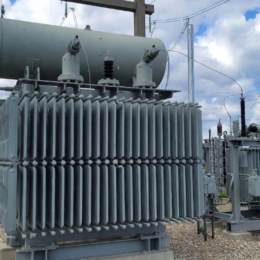
Once the data package is available, ask for a written response tied to the proposed transformer. The response should explain the assessed duty and its limitations, rather than rely on a general description of converter service.
Agree the loading and thermal evidence
Request the assessment method, waveform input revision, loading assumptions and allowable operating conditions. Ask which temperature criteria and cooling conditions apply, and how the proposed construction is represented in the assessment. Record any restrictions that must carry into the operating instructions.
Do not substitute an arbitrary percentage reduction in nameplate capacity for this review. Likewise, an acceptable fundamental-frequency kVA calculation does not document how the nonsinusoidal current duty has been assessed. Keep the harmonic assessment attached to the broader transformer rating decision.
Use K-factor within its limits
Schneider Electric’s K-factor explanation describes weighting harmonic currents for their heating effect in its low-voltage transformer context. Its separate comparison of K-rated and harmonic-mitigating transformers explains that a K-rating does not itself reduce THD.
This distinction matters when reviewing a bid. “Can tolerate the specified harmonic duty” and “will reduce distortion at an agreed system location” require different evidence. Ask the supplier to state which function the proposal addresses and how it was assessed.
Avoid specifying K-9, K-13 or K-20 simply because the installation is a BESS. If a K-factor is used, request the spectrum and calculation basis, its relevance to the proposed equipment, and the resulting duty limitations. A single THD value is not a complete substitute for those inputs.
Confirm winding and converter-interface assumptions
Hitachi Energy’s solar and BESS transformer application overview identifies harmonics and fast switching among the application concerns. Ask the PCS and transformer suppliers to agree the relevant interface information, including winding connections, grounding and any required switching-related assessment.
Do not assume that a delta winding, a selected vector group or higher transformer impedance will solve all harmonic issues. Require the proposed arrangement to be represented in the project assessment. For split-winding or other converter arrangements, confirm that the chosen assessment method covers the equipment being supplied.
Record the standard and edition agreed for each purpose. IEC 61378-1:2011 has a published scope covering transformers for industrial converter plants; that scope is a reason to check applicability, rather than declare it mandatory for every BESS.
Standards status note: IEEE lists a C57.110 revision project with project authorization approved on February 12, 2026. A revision project is not a newly published replacement standard. Keep the contract’s edition and equipment applicability explicit.
Check network interaction across operating modes
The system study should identify the network assumptions used alongside the PCS data. Ask the study engineer which background distortion, network impedance conditions, equipment configurations and filter states are relevant to the connection assessment.
There is a useful published example in K. Ozer and T. P. Rastall’s IPST2025 BESS harmonic filter case study, presented at the June 8–12, 2025 conference. The authors investigated a UK BESS using measurements in charging, discharging and idle operation. They validated a network model against site measurements and considered background network characteristics when developing a site-specific filter solution.
The transferable lesson is the investigation method. The paper’s filter design and UK assessment conditions are not specifications for another plant, and the project is not an Eilite customer case.
Use the intended operating duty to select study cases. Ask whether the assessment needs to cover different active/reactive power states, numbers of PCS units online and network conditions. The engineer should document why the selected cases represent the project and identify remaining exclusions.
For a solar-plus-storage installation, coordinate the solar transformer interfaces with the storage equipment. Do not assume that a PV inverter report describes the battery PCS or that it covers the combined plant’s operating states.
Illustrative scenario: A PCS firmware or filter revision changes after the harmonic study is issued. Record the change and ask the responsible engineers whether the previous inputs and conclusions remain valid. An unchanged transformer nameplate does not settle whether the interface evidence still represents the installed system.
Agree acceptance evidence before procurement
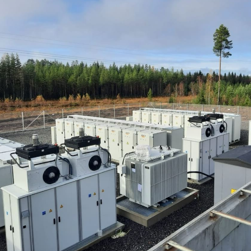
Define the evidence needed to close each harmonic-interface responsibility before placing the order. The table below is a starting point for agreeing responsibility; the project contracts should identify the actual accountable parties.
| Interface responsibility | Evidence to request | Closeout question |
|---|---|---|
| PCS supplier | Configuration-specific waveform data, operating conditions and report limitations | Does the package represent the PCS configuration to be installed? |
| Transformer supplier | Design-basis response, assessed duty, restrictions and agreed factory evidence | Has the transformer been assessed against the accepted waveform package? |
| Grid-study engineer | Study assumptions, model basis, operating cases and compliance results | Does the assessment address the applicable connection criteria and boundary? |
| EPC or integration lead | Coordinated document revisions, action register and site verification plan | Do the supplier responses, study and installed arrangement agree? |
Separate factory evidence from site verification
Ask what the agreed transformer factory tests demonstrate and what remains covered by design assessment or site measurements. Do not describe a routine factory test under sinusoidal conditions as proof of every operating waveform or of whole-plant PCC compliance. If a special test is proposed, agree its method, acceptance criteria and availability with the supplier.
For site verification, define measurement locations, operating states, instrumentation requirements, assessment method and acceptance criteria with the responsible engineer. Assign ownership for reviewing the results and resolving deviations. A test report should make clear which equipment configuration and conditions it represents.
Close the interface with a short checklist
Before releasing the harmonic specification, confirm:
- Which PCS waveform report and equipment revisions form the design basis?
- Which charge, discharge, reactive and idle conditions are included or excluded?
- What transformer assessment, operating limitations and supporting evidence have been accepted?
- Which grid requirements and measurement locations apply?
- Who owns model validation, mitigation decisions and site acceptance?
- Who reviews changes to firmware, filters, winding arrangements or the number of PCS blocks?
Keep open actions visible. Missing project data should remain an assigned engineering action until the responsible party supplies or approves it.
Common questions about BESS transformer harmonics
Does a K-rated transformer reduce THD?
A K-rating addresses harmonic heating tolerance; it does not by itself demonstrate distortion reduction. Require separate evidence if harmonic mitigation is part of the proposal, including the location and operating conditions for the claimed result.
Is a rated-power PCS distortion figure enough?
It is useful information, but it is not the full interface package. Request the spectrum, current base, equipment configuration and relevant operating cases so the transformer and system assessments have traceable inputs.
Does PCC compliance prove transformer suitability?
PCC compliance addresses the agreed system harmonic requirements. Transformer suitability needs its own assessment against the current duty and operating conditions. Maintain separate closeout evidence for both.
Should idle and reactive operation be reviewed?
Ask the project engineer to assess whether those permitted modes belong in the study and acceptance plan. The IPST2025 example included idle measurements, but it does not establish one universal test matrix for all BESS installations.
For a project discussion, share your PCS AC data, harmonic report, single-line diagram and intended duty. Include the applicable connection requirements and unresolved interface questions so the inquiry starts from the equipment and operating conditions that matter.